Memory parameter configuration method and electronic device
A parameter configuration method and technology for electronic equipment, applied in the computer field, can solve problems such as poor reliability, difficulty in meeting requirements for embedded equipment, and memory timing parameters easily affected by environmental factors, so as to achieve the effect of speeding up startup and avoiding accidental factors.
- Summary
- Abstract
- Description
- Claims
- Application Information
AI Technical Summary
Problems solved by technology
Method used
Image
Examples
no. 1 example
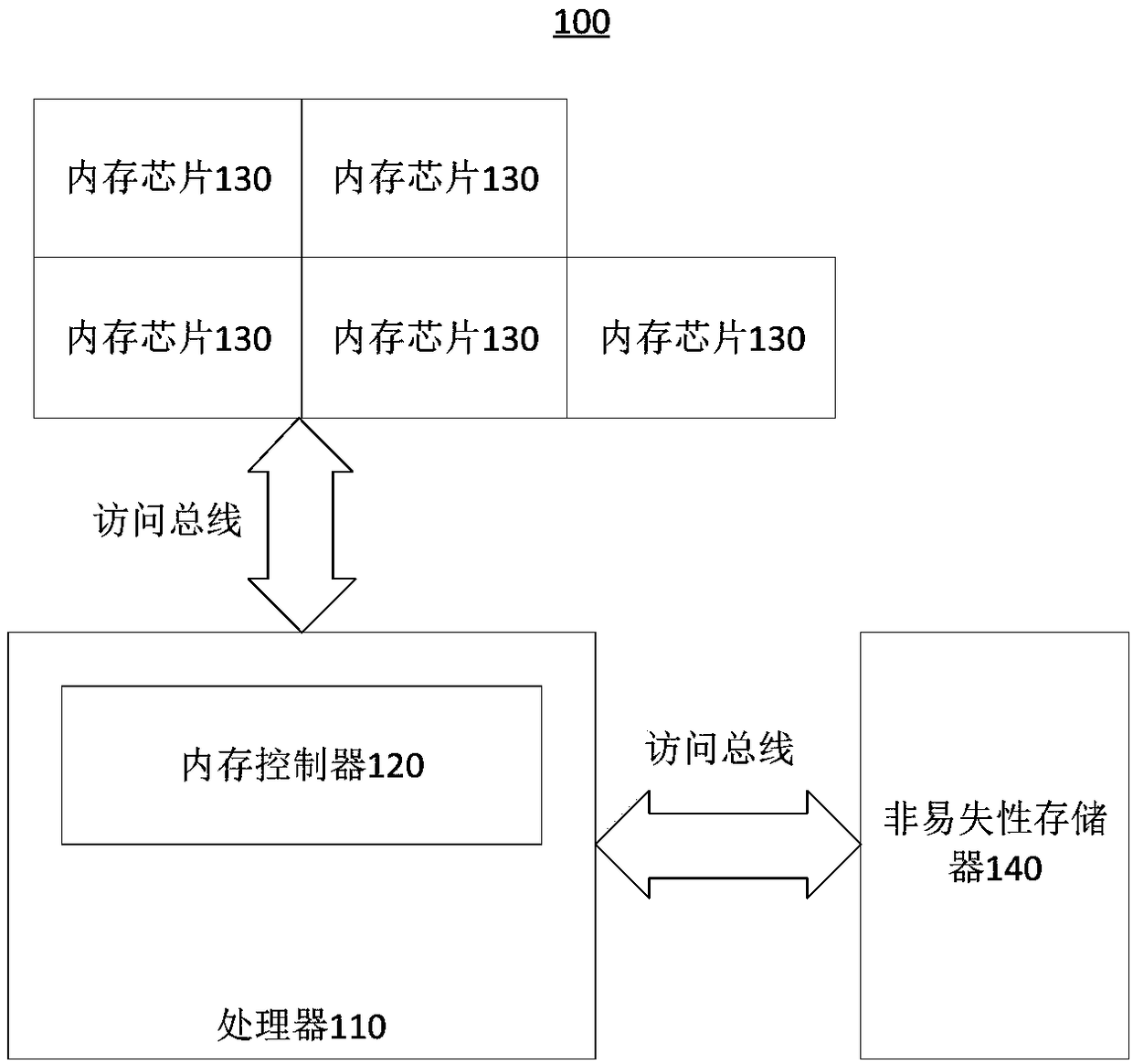
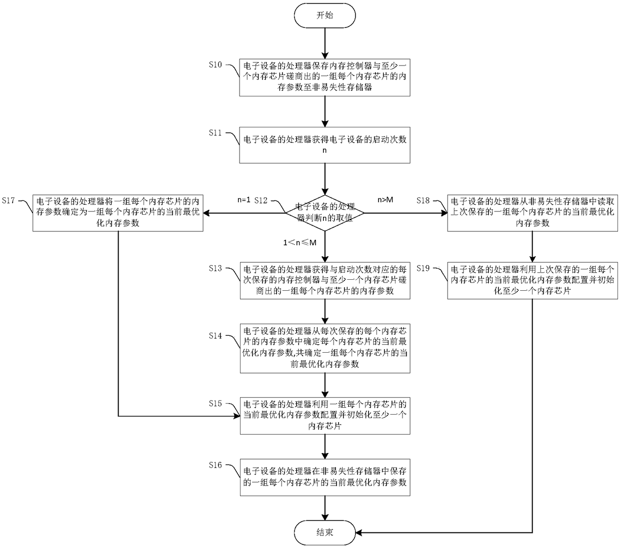
[0061] figure 2 A flow chart of the memory parameter configuration method provided by the first embodiment of the present invention is shown. figure 2 The method in will be executed every time the electronic device 100 is started, and the description below takes one of the start-up processes as an example. refer to figure 2 , the method includes:
[0062] Step S10 : the processor 110 of the electronic device 100 saves a set of memory parameters of each memory chip 130 negotiated by the memory controller 120 and at least one memory chip 130 to the non-volatile memory 140 .
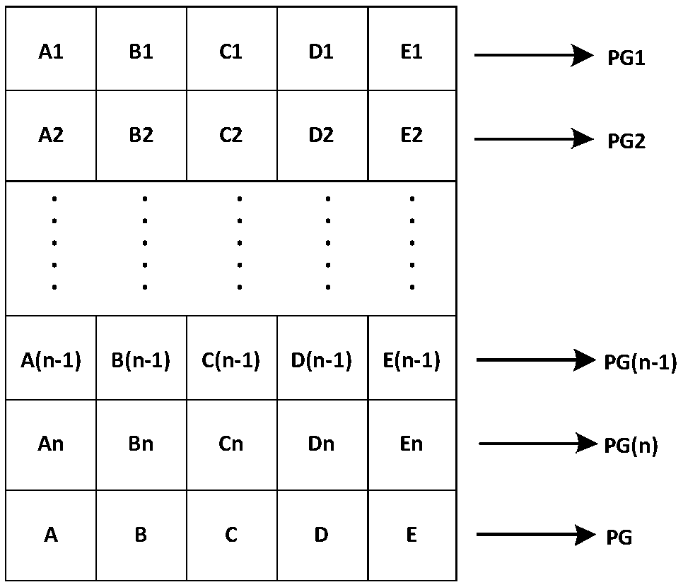
[0063] The memory chip 130 has multiple parameters, but usually the memory parameters that can be obtained through negotiation mainly refer to memory timing parameters. The memory timing parameter is generally an integer, and each memory chip 130 corresponds to a memory timing parameter. When memory parameters are mentioned later, memory timing parameters are generally taken as an example. For other n...
no. 2 example
[0097] Figure 4 A flow chart of the memory parameter configuration method provided by the second embodiment of the present invention is shown. refer to Figure 4 , Figure 4 The method shown and image 3 The methods shown are relatively similar in nature.
[0098] Step S20 to step S21 are similar to step S10 to step S11, and step S22 is similar to step S12, but only two situations are judged in step S22, i.e. two situations of n=1 and n>1, wherein n=1, execute step S26, when n>1, execute step S23.
[0099] Step S23 to step S25 are similar to step S13 to step S15, and step S26 is similar to step S17. There is no step corresponding to step S16 in the second embodiment, because the second embodiment does not use a set of historical memory parameters ( Figure 4 There is no n>M branch in ).
[0100] Step S50 is similar to step S20, step S51 is similar to step S21, step S42 is similar to step S22, and step S53 is similar to step S23. There is no step corresponding to step ...
no. 3 example
[0104] The third embodiment of the present invention provides an electronic device 100, including a processor 110, at least one memory chip 130 and a memory controller 120;
[0105] The processor 110 is configured to save a set of memory parameters of each memory chip 130 negotiated by the memory controller 120 and at least one memory chip 130 each time the electronic device 100 is started,
[0106] Obtain the startup times of the electronic device 100,
[0107] When it is judged that the number of startups is less than the threshold of startup times, a set of memory parameters of each memory chip 130 negotiated by the memory controller 120 and at least one memory chip 130 corresponding to the number of startups is obtained,
[0108] Determine the current optimized memory parameters of each memory chip 130 from the saved memory parameters of each memory chip 130 each time, and determine a set of currently optimized memory parameters for each memory chip 130 for at least one memo...
PUM
 Abstract
Description
Claims
Application Information
 - R&D
- Intellectual Property
- Life Sciences
- Materials
- Tech Scout
- Unparalleled Data Quality
- Higher Quality Content
- 60% Fewer Hallucinations
Browse by: Latest US Patents, China's latest patents, Technical Efficacy Thesaurus, Application Domain, Technology Topic, Popular Technical Reports.
© 2025 PatSnap. All rights reserved.Legal|Privacy policy|Modern Slavery Act Transparency Statement|Sitemap|About US| Contact US: help@patsnap.com


