Catalytic combustion inerting oil tank device and method thereof

A fuel tank and fuel technology, which is applied in the layout, power plant, fuel tank safety measures, etc. combined with the fuel supply of the internal combustion engine, can solve the problems of low efficiency, narrow application scope and high price of nitrogen inerting technology, and achieve pure gas source. The effect of low degree requirements, fast startup speed and high reliability

Inactive Publication Date: 2015-08-19
NANJING UNIV OF AERONAUTICS & ASTRONAUTICS
View PDF5 Cites 26 Cited by
  • Summary
  • Abstract
  • Description
  • Claims
  • Application Information

AI Technical Summary

Problems solved by technology

[0008] The purpose of the present invention is to overcome the shortcomings of low efficiency, high price and narrow application range of nitrogen production inerting technology, based on catalytic combustion, to provide a device and method for catalytic combustion inerting oil tank

Method used


Image

  • Catalytic combustion inerting oil tank device and method thereof
  • Catalytic combustion inerting oil tank device and method thereof

Examples


Embodiment 1

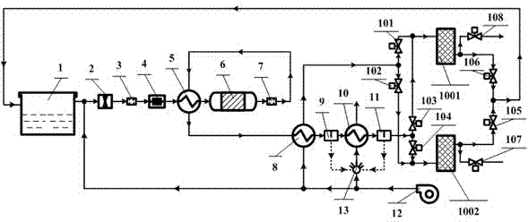
[0032] figure 1 It is a schematic flow diagram of the device for flushing the upper gas phase space of the inerted fuel tank by catalytic combustion in the present invention. The gas outlet of the fuel tank 1 is respectively connected with the inlet of the air pump 2, the inlet of the desorption heater 8, the inlet of the water sprayer 13 and the outlet of the fan 12 through pipelines; The air pump 2, the first flame arrester 3, the electric heater 4, the cold side channel of the preheater 5 and the catalytic reactor 6 are connected in sequence through pipelines between the outlet of the second flame arrester 7; Between the outlet of the second flame arrester 7 and the gas inlet of the second water separator 11, there are sequentially connected the hot side channel of the preheater 5, the hot side channel of the desorption heater 8, the gas channel of the first water separator 9 and the gas inlet of the second water separator 11. The hot side channel of the inert gas cooler 10...

Embodiment 2

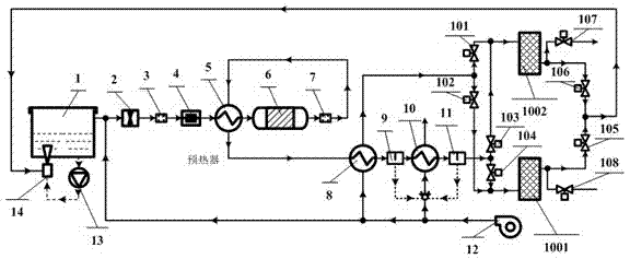
[0043] This implementation is applied to washing the fuel oil stored on the ground, and the fuel tank 1 is an oil storage tank container, combined with figure 2 It can be seen that the difference between this device and Embodiment 1 is that a scrubber injector 14 is placed at the bottom of the fuel tank 1, and an oil pump 13 is connected through a pipeline between the fuel outlet at the bottom of the fuel tank 1 and the fuel inlet of the scrubber injector 13. The outlet of the device 13 is below the lowest liquid level at the bottom of the oil tank 1, and the gas inlet of the washing injector 13 is connected with the outlet of the fifth shut-off valve 105 and the outlet of the sixth shut-off valve 106 through pipelines.

[0044] The working process of this implementation is as follows:

[0045] The slightly water content inert mixture exiting from the outlet of the fifth shut-off valve 105 and the outlet of the sixth shut-off valve 106 is sent into the scrubbing injector 13, ...


PUM


Abstract

The invention discloses a catalytic combustion inerting oil tank device and a method thereof. According to the method, a mixture composed of fuel steam and gas on the upper portion of an oil tank is pumped out and then mixed with the outside air, the mixture enters a catalytic reactor to conduct flameless combustion after being subjected to electric heating and temperature rising through a preheater, carbureted hydrogen in the fuel steam is oxidized to be carbon dioxide and water, gas flowing out of a catalytic reactor outlet is firstly cooled, most water is removed, then the gaseous water vapor is removed out of the gas through two adsorbers working in an intermittent mode, then the gas returns to the upper portion of the oil tank to conduct flushing and inerting, or the gas enters a washing injector to be mixed with fuel to enter the bottom of the oil tank to conduct washing and inerting on the fuel. By the adoption of the technical scheme, fuel steam is converted to be carbon dioxide through a catalytic combustion technology to inert the oil tank, so that the requirement for the gas source purity is low, high-pressure gas guide is not needed, preheating of a film separation device is not needed, and the catalytic combustion inerting oil tank device is high in starting speed, short in inerting time, simple in device structure and and high in reliability.

Description

technical field [0001] The invention belongs to the technical field of fire prevention and explosion protection, and in particular relates to a device and method for catalytic combustion inerting an oil tank. Background technique [0002] Due to the action of external ignition sources, such as lightning, static electricity, open flame, heating, etc., the fuel tank will burn and explode, resulting in casualties or property damage. Therefore, how to effectively avoid the safety issue of fuel tank combustion and explosion has been widely concerned by the society. [0003] Take the problem of incendiary explosions in aircraft as an example. In the Vietnam War, the U.S. Air Force lost thousands of aircraft due to ground fire. Among these losses, the proportion of losses due to fuel oil fires is as high as 50%. According to the statistics of 3,726 civil aircraft accidents worldwide from 1966 to 2009 by the Cabin Safety Research Technical Group (CSRTG), a total of 370 accidents w...

Claims


Application Information

Patent Timeline
Patent Type & Authority Applications(China)
IPC IPC(8): B64D37/32B64D37/06B60K15/077B63H21/38
Inventor 冯诗愚李超越刘卫华
Owner NANJING UNIV OF AERONAUTICS & ASTRONAUTICS
Why Eureka
Try Eureka