Printing and dyeing wastewater autotrophic denitrification denitriding device and method

A technology for autotrophic denitrification, printing and dyeing wastewater, applied in the textile industry wastewater treatment, anaerobic digestion treatment and other directions, can solve the problem of TN exceeding the standard in the effluent, and achieve the effects of short residence time, low operating cost and small footprint

Active Publication Date: 2016-06-01
UNIV OF SCI & TECH BEIJING +2
View PDF2 Cites 25 Cited by
  • Summary
  • Abstract
  • Description
  • Claims
  • Application Information

AI Technical Summary

Problems solved by technology

[0005] Aiming at the problem that the TN of the effluent exceeds the standard due to insufficient heterotrophic denitrification carbon source in the printing and

Method used


Image

  • Printing and dyeing wastewater autotrophic denitrification denitriding device and method
  • Printing and dyeing wastewater autotrophic denitrification denitriding device and method

Examples


Embodiment 1

[0024] Example 1: Rapid start-up of the reactor

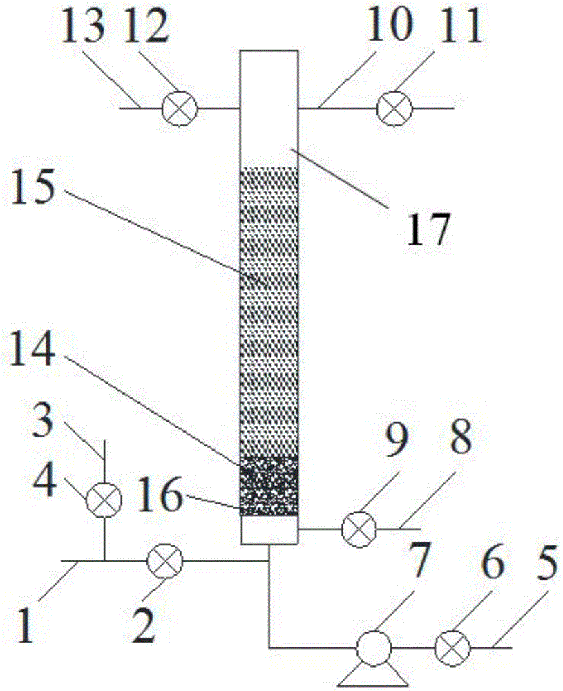
[0025] The test equipment used in the test is as figure 1 As shown, the device takes the secondary effluent of a printing and dyeing wastewater treatment plant in Wuxi as the treatment object. Close all valves on the device first, then fill pyrite and sulfur fillers in layers at a volume ratio of 1:5, first fill pyrite and then sulfur, and the distance between the top layer of filler and the water outlet accounts for 10% of the height of the entire reactor. After the packing is filled, open the water inlet valve 2 and the water outlet valve 11, and the override pipe valve 4, the backwash water inlet valve 6, the vent valve 9 and the backwash water outlet valve 12 are still closed, and the secondary outlet water enters the reaction device through the water inlet pipe 1 , and pass through the filter plate and the long-handle filter head 16, the pyrite packing layer 14 and the sulfur packing layer 15 in turn, and finally discharg...

Embodiment 2

[0027] Example 2: Denitrification of printing and dyeing wastewater with high hydraulic load

[0028] After the successful start-up of the reactor in Example 1, the test was continued.

[0029] The device takes the secondary effluent of a printing and dyeing wastewater treatment plant in Wuxi as the treatment object. The operating parameters are: empty bed residence time 20min, hydraulic load 43.2m 3 / (m 2 d), influent TN is 19.53mg / L, NO 3 - -N is 17.78mg / L, effluent TN is 5.93mg / L, TN removal rate is 69.7%, effluent TN is far better than the first-class A standard and Discharge standards in "Discharge Limits of Main Water Pollutants from Urban Sewage Treatment Plants and Key Industries in Taihu Lake Area" (DB32 / T1072-2007).

Embodiment 3

[0030] Example 3: Nitrogen removal of simulated wastewater with high hydraulic load

[0031] After the successful start-up of the reactor in Example 1, the test was continued.

[0032] The test water is artificially prepared simulated wastewater, and the operating parameters are: the empty bed residence time is 20 minutes, and the hydraulic load is 43.2m 3 / (m 2 d), influent TN is 25.35mg / L, NO 3 - The -N is 23.43mg / L, the effluent TN is 2.16mg / L, and the TN removal rate is 91.5%, realizing efficient denitrification.


PUM


Abstract

The invention provides a printing and dyeing wastewater autotrophic denitrification denitriding device and method, and belongs to the technical field of printing and dyeing wastewater treatment. NO3--N (nitric nitrogen) in water is reduced into N2 via autotrophic denitrifying bacteria by taking reduced sulfur and iron as the electron donor, so that denitriding is realized. According to the printing and dyeing wastewater autotrophic denitrification denitriding device and method, through the combined packing of pyrite and sulphur and the optimum mixture ratio, the advantages of high nitrogen removal efficiency and little changes in effluent pH are achieved, and in addition, the advantages of high starting speed, no inoculated sludge and long backwashing period are also achieved; moreover, according to the TN (Total Nitrogen) condition of secondary effluent of a printing and dyeing wastewater treatment plant, the scheme that the device operates when TN exceeds the standard and stops operating when TN is up to the standard is adopted, so that secondary effluent can directly skip over the device to enter the next treatment unit or be directly discharged, and the advantages of flexible operation mode and low operating cost are achieved.

Description

technical field [0001] The invention relates to the technical field of printing and dyeing wastewater treatment, in particular to an autotrophic denitrification device and method for printing and dyeing wastewater. Background technique [0002] Textile printing and dyeing is one of the key industries for industrial pollution prevention and water conservation. Textile printing and dyeing wastewater accounts for 8% of the total industrial wastewater discharge in the country, of which chemical oxygen demand (COD) and ammonia nitrogen discharge account for 9% of the total industrial discharge in the country and 3% are the No. 4 heavy polluting industries. Printing and dyeing is the post-processing process of textile products. It is the key for the textile industry to adapt to and satisfy consumption, start the market, and increase economic benefits. However, printing and dyeing is also the most polluting process in the textile industry, and the wastewater discharge accounts for ...

Claims


Application Information

Patent Timeline
IPC IPC(8): C02F3/28C02F103/30
CPCC02F3/28C02F2103/30
Inventor 马方曙周北海潘永月袁蓉芳徐岷杨曹玲许志红陈纯
Owner UNIV OF SCI & TECH BEIJING
Why Eureka
Try Eureka