A winding automatic shaping device

A shaping device and fully automatic technology, which is applied in the field of transformer manufacturing, can solve the problems of re-turning of windings, direct placement of windings, difficulties, etc., and achieve the effects of reducing labor intensity, convenient transportation, and simple structure

Active Publication Date: 2020-05-29
常德国力变压器有限公司
View PDF7 Cites 0 Cited by
  • Summary
  • Abstract
  • Description
  • Claims
  • Application Information

AI Technical Summary

Problems solved by technology

The current winding shaping device uses cylinders or hydraulic cylinders to compress the windings. This method has relatively large disadvantages. Expansion and deformation, so that the winding cannot be placed on the iron core, making the winding a defective product, which greatly reduces the qualified rate of the winding and reduces the profit margin of the product. At the same time, the current compression device cannot directly place the winding on the compression by driving. On the device, it is necessary to manually place the winding on the pressure-bearing mechanism of the pressing device. At the same time, after pressing one side, it also needs to be turned over many times. The steps are cumbersome and the winding is heavy and difficult to turn over.

Method used


Image

  • A winding automatic shaping device
  • A winding automatic shaping device
  • A winding automatic shaping device

Examples


Embodiment 1

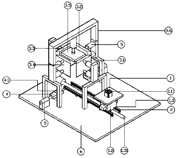
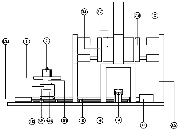
[0019] Embodiment one; figure 1 , 2 , 3, 4, and 5, a fully automatic winding shaping device, including a pressure bearing plate 1, a slide rail 2, and a shaping device 3, wherein the pressure bearing plate 1 is a rectangular plate, and the top of the pressure bearing plate 1 is fixed with a positioning The column 1.1, the positioning column 1.1 includes the sliding plate 1.11 and the adjusting screw 1.13 around, and the upper and lower ends of the inner wall of each sliding plate 1.11 are hinged with linkage rods 1.12, and every four linkage rods 1.12 are located at the upper end of the sliding plate 1.11 The other end is hinged on the same sleeve, and the other end of every four linkage rods 1.12 located at the lower end of the sliding plate 1.11 is also hinged on the same sleeve. The same adjustment screw 1.13 is inserted into the two sleeves and the adjustment screw 1.13 The two sleeves are threaded, and the bottom of the adjustment screw 1.13 is rotatably fixed at the cen...

Embodiment 2

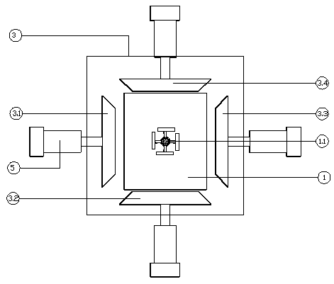
[0020] Embodiment two; Image 6 As shown, the first shaping plate 3.1, the second shaping plate 3.2, the third shaping plate 3.3, and the fourth shaping plate 3.4 all include the middle vertical plate 3.7 and the splicing plate 3.8, wherein the vertical plate 3.7 is located in the middle and the back side of the vertical plate 3.7 Cylinder 5 is fixed, and is formed by splicing plate 3.8 on both sides of vertical plate 3.7, wherein between splicing plate 3.8 and vertical plate 3.7 is fastened by threaded tie rod 3.9; Horizontal hole is drilled on each vertical plate 3.7, A horizontal hole is also drilled on each splicing plate 3.8, and the threaded tie rod 3.9 is inserted into the hole of the splicing plate 3.8 and the vertical plate 3.7, and then tightened by the threaded pull rod 3.9, so that the splicing plate 3.8 and the vertical plate 3.7 are fixed together In this way, the widths of the first shaping plate 3.1, the second shaping plate 3.2, the third shaping plate 3.3, an...


PUM


Abstract

The invention discloses a winding automatic shaping device. The device includes a pressure-bearing plate, slide rails, and a shaping device, wherein the pressure-bearing plate is a rectangular plate,A locate upright column is fixed on that top of the pressure plate, A slider is arranged below the pressure plate, A slide rail is arranged at the bottom of the slide block and matched with the slideblock, top blocks are respectively arranged on both sides of one end of the slide rail, A lifting device correspond to that top position is arranged between the slide block and the pressure bearing plate, A shaping device is arranged above one end of the slide rail provided with a top block, The shaping device comprises a shaping plate all around, a pressing plate on the top and an air cylinder driving each shaping plate and the pressing plate, wherein each shaping plate is a trapezoidal block and the inclined surfaces of each two trapezoidal blocks are in contact with each other, the pressingplate is a rectangular pressing plate and the threaded cooperation is arranged between the pressing plate and the piston rod of the cylinder; The outer circumference and the upper and lower end facesof the winding can be shaped at one time, so that the step of flipping the winding is omitted. Winding deformation due to excessive extrusion of the shaping plate is prevented.

Description

technical field [0001] The invention relates to the field of transformer manufacturing, in particular to an automatic winding shaping device. Background technique [0002] When the copper wire is wound into a winding, due to the springback characteristics of the copper wire, the size of the wound winding is out of tolerance (the outer dimension of the product exceeds the tolerance range specified by the product standard), so the winding needs to be reshaped before it can be placed on the iron on the core. The current winding shaping device uses cylinders or hydraulic cylinders to compress the windings. This method has relatively large disadvantages. For example, when the pressure exerted by the compressing device on the winding exceeds the yield strength of the winding, the winding will move toward the center. Expansion and deformation, so that the winding cannot be placed on the iron core, making the winding a defective product, which greatly reduces the qualified rate of ...

Claims


Application Information

Patent Timeline
Patent Type & Authority Patents(China)
IPC IPC(8): H01F41/04
CPCH01F41/04
Inventor 贵体仁黄浩锐李建奇杨民生张家跃肖健陈真生
Owner 常德国力变压器有限公司
Why Eureka
Try Eureka