Current Mode Residual Amplifier

A technology of amplifier and current mode, which is applied in the direction of amplifiers, analog-to-digital converters, components of amplifiers, etc., and can solve problems such as fast speed and limitation

Active Publication Date: 2018-12-11
NO 24 RES INST OF CETC
View PDF7 Cites 0 Cited by
  • Summary
  • Abstract
  • Description
  • Claims
  • Application Information

AI Technical Summary

Problems solved by technology

Switched capacitor headroom amplifiers require fine timing to control the transfer of their charges, so complex timing design circuits are required. At the same time, bec

Method used


Image

  • Current Mode Residual Amplifier
  • Current Mode Residual Amplifier
  • Current Mode Residual Amplifier

Examples


Embodiment Construction

[0018] In order to make the technical means, creative features, goals and effects achieved by the present invention easy to understand, the present invention will be further described below in conjunction with specific illustrations.

[0019] In the description of the present invention, it should be noted that unless otherwise specified and limited, the terms "installation", "connection" and "connection" should be understood in a broad sense, for example, it can be a fixed connection or a detachable connection. Connected, or integrally connected; it may be mechanically connected or electrically connected; it may be directly connected or indirectly connected through an intermediary, and it may be the internal communication of two components. Those of ordinary skill in the art can understand the specific meanings of the above terms in the present invention in specific situations.

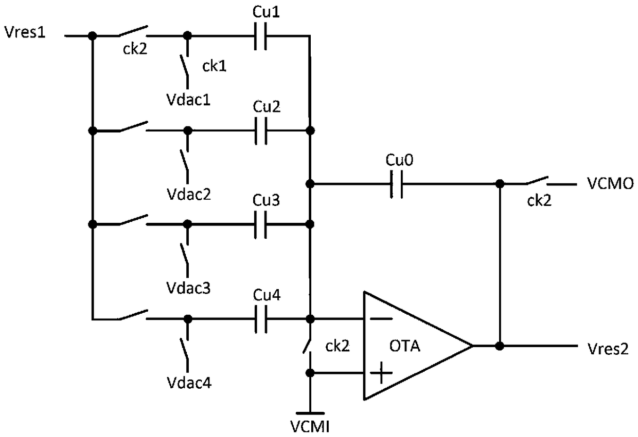
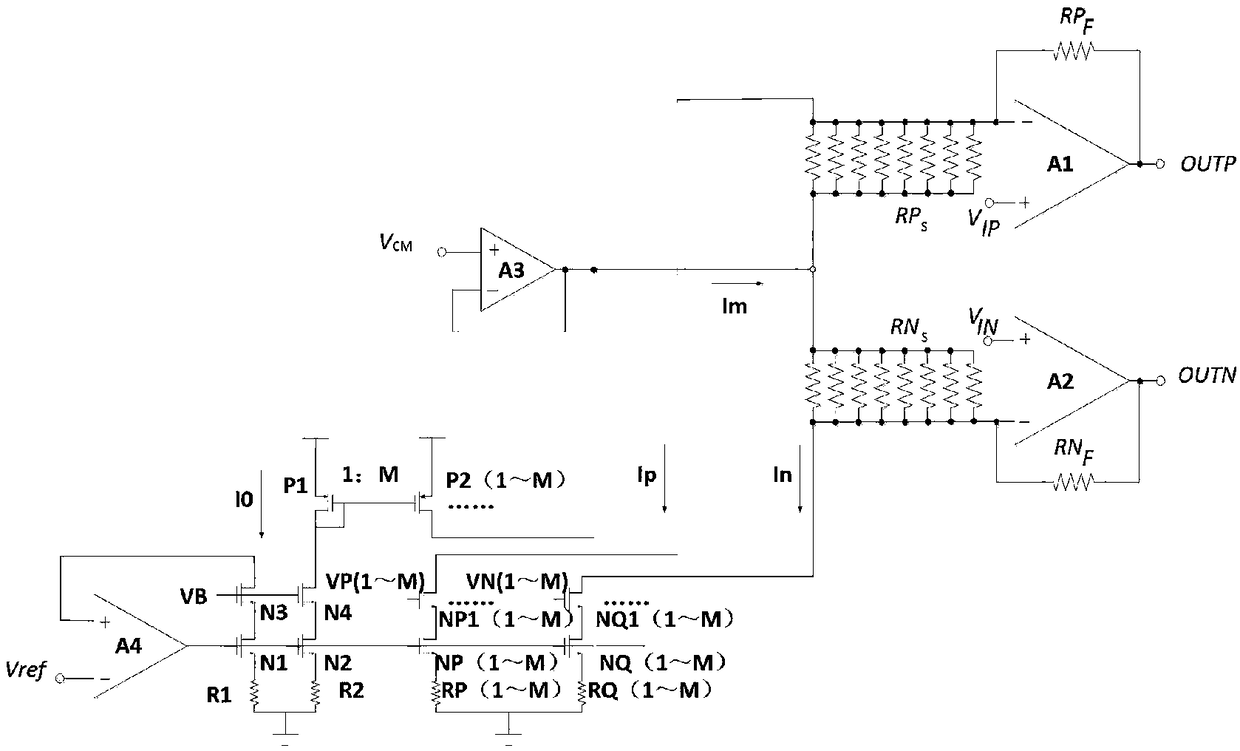
[0020] Please refer to image 3 As shown, it is a circuit diagram of a preferred embodiment of a ...


PUM


Abstract

The invention discloses a current mode residual amplifier, which comprises a reference current source, a switching current digital-to-analog converter and a resistor feedback amplification network. The reference current source is connected with a switching circuit digital-to-analog converter and a resistor feedback amplification network, and the switching circuit digital-to-analog converter is also connected with an electronic feedback amplification network. The reference current source is used for generating a reference current, the switching current digital-to-analog converter is used for generating an analog current signal, and the resistor feedback amplification network is used for converting the current signal into a voltage signal through a resistor, and amplifying the voltage valueresidual to be suitable for subsequent pipeline to continue quantization conversion. The invention simplifies the timing design of the residual amplifier in the production line analog-to-digital converter, improves the speed of the residual amplifier, and has the advantages of simple sequential circuit design, fast conversion speed and the like compared with the traditional structure. The amplifier can be widely used in analog-to-digital converter systems.

Description

technical field [0001] The invention belongs to a current mode residual gain amplification system, in particular to a current mode residual amplifier. Background technique [0002] In the pipeline type analog-to-digital converter, the most important module is the residual amplifier. The function of the residual amplifier is to amplify the difference margin between the input signal and the analog value corresponding to the rough quantized signal, and its purpose is to calculate the residual volume and zoom in. In the residual amplifier, a sub-analog-to-digital converter is used to roughly quantize the input analog signal, and then the coarse-quantized signal is converted into an analog signal through a digital-to-analog converter, and the addition and subtraction of the input signal and the coarse quantization signal are realized through the analog network , in the margin amplifier, it is also necessary to amplify the margin generated after addition and subtraction, so as to...

Claims


Application Information

Patent Timeline
IPC IPC(8): H03M1/12H03F1/34
CPCH03F1/342H03M1/12
Inventor 邓民明刘涛王旭石寒夫付东兵陈光炳王健安
Owner NO 24 RES INST OF CETC
Why Eureka
Try Eureka