An ultra-wideband Ka-band up-conversion system and method

An ultra-wideband, ka-band technology, applied in the field of ultra-wideband Ka-band up-conversion systems, can solve problems such as ultra-wideband millimeter-wave signal generation, and achieve the effects of suppressing spurs, reducing hardware complexity and cost, and high stability

Inactive Publication Date: 2018-12-11
BEIJING INST OF RADIO MEASUREMENT
View PDF7 Cites 5 Cited by
  • Summary
  • Abstract
  • Description
  • Claims
  • Application Information

AI Technical Summary

Problems solved by technology

[0005] The purpose of the present invention is to provide an ultra-wideband Ka-band up-conversion system and method to solve the problem of ultra-wideband millimeter wave signal generation by using the first frequency conversion unit, the second frequency conversion unit and the amplification unit technology

Method used


Image

  • An ultra-wideband Ka-band up-conversion system and method
  • An ultra-wideband Ka-band up-conversion system and method

Examples


Embodiment Construction

[0033] In order to illustrate the present invention more clearly, the present invention will be further described below in conjunction with preferred embodiments and accompanying drawings. Similar parts in the figures are denoted by the same reference numerals. Those skilled in the art should understand that the content specifically described below is illustrative rather than restrictive, and should not limit the protection scope of the present invention.

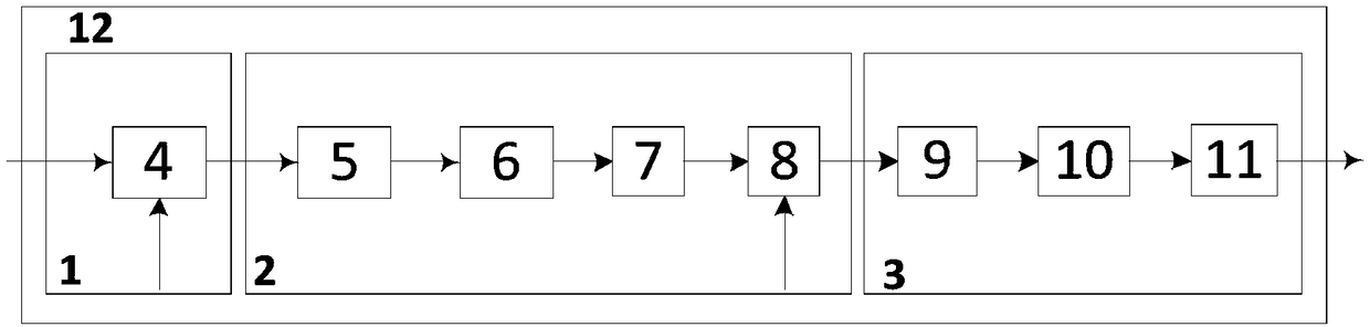
[0034] Such as figure 1 As shown, an ultra-wideband Ka-band up-conversion system 12 disclosed in the present invention includes: a first frequency conversion unit 1, a second frequency conversion unit 2 and an amplification unit 3; wherein,

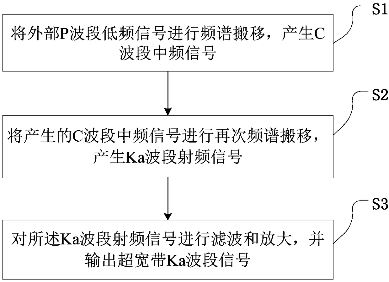
[0035] The first frequency conversion unit 1 is used to shift the spectrum of the external P-band low-frequency signal to generate a C-band intermediate frequency signal;

[0036] The second frequency conversion unit 2 is used to re-spectrum shift the generated C-band intermediate fr...


PUM


Abstract

The invention discloses an ultra-wideband Ka-band up-conversion system and method, the system comprises a first conversion unit, a second conversion unit and an amplification unit; wherein the first frequency conversion unit is used for spectrum shifting of the external P-band low-frequency signal to generate a C-band intermediate frequency signal; The second frequency conversion unit is used forspectrum shifting of the generated C-band intermediate frequency signal again to generate a Ka-band radio frequency signal; the amplifying unit is used for filtering and amplifying the Ka-band radio frequency signal and outputting the ultra-wideband Ka-band signal. The technical proposal of the invention can avoid using expensive high-frequency devices, greatly reduces the hardware complexity andcost of the emitter, at the same time can restrain the scatter in the link, the stability of the output Ka-band radio frequency signal is high, and the debugging operation is simple.

Description

technical field [0001] The invention relates to the field of microwave communication. More specifically, it relates to an ultra-wideband Ka-band up-conversion system and method. Background technique [0002] The up-conversion system is the core component of the radar system. Its function is to move the spectrum of the baseband signal to the high frequency band. Its performance directly determines the quality of the radar system. In order to reduce the cost of radar manufacturing, radar systems at home and abroad are gradually developing rapidly in the direction of small size and light weight, integration and solid state. [0003] Higher communication data rates can be achieved using wider bandwidths. The information carried by the signal is usually modulated within the nearby bandwidth based on the carrier. For the same information and the same bandwidth, a higher carrier frequency means a smaller relative bandwidth. That is to say, at higher frequencies, the same relativ...

Claims


Application Information

Patent Timeline
Patent Type & Authority Applications(China)
IPC IPC(8): H04B1/04
CPCH04B1/04H04B2001/0408
Inventor 王彦炜
Owner BEIJING INST OF RADIO MEASUREMENT
Why Eureka
Try Eureka