Punching machine for bolt machining

A stamping machine and bolt technology, applied in the field of mechanical processing equipment, can solve the problems of small application range, inconvenient die replacement, single bolt type, etc., and achieve the effect of strong practicability and simple structure

Inactive Publication Date: 2018-12-14
ANHUI LIUFANG ZHONGLIAN MECHANICAL SHARE
View PDF7 Cites 10 Cited by
  • Summary
  • Abstract
  • Description
  • Claims
  • Application Information

AI Technical Summary

Problems solved by technology

The defect of the present punching machine is that the die is fixedly arranged on the workbench of the punching machine, and the die is not easy to replace, which leads to a single type of bolt punched by the punching machine, and each punching machine is only suitable for punching one bolt. This type of bolt has a small scope of application
Based on this situation, in existing enterprises, multiple stamping machines are used to stamp different types of bolts, which leads to an increase in the cost of the enterprise

Method used


Image

  • Punching machine for bolt machining
  • Punching machine for bolt machining
  • Punching machine for bolt machining

Examples


Embodiment 1

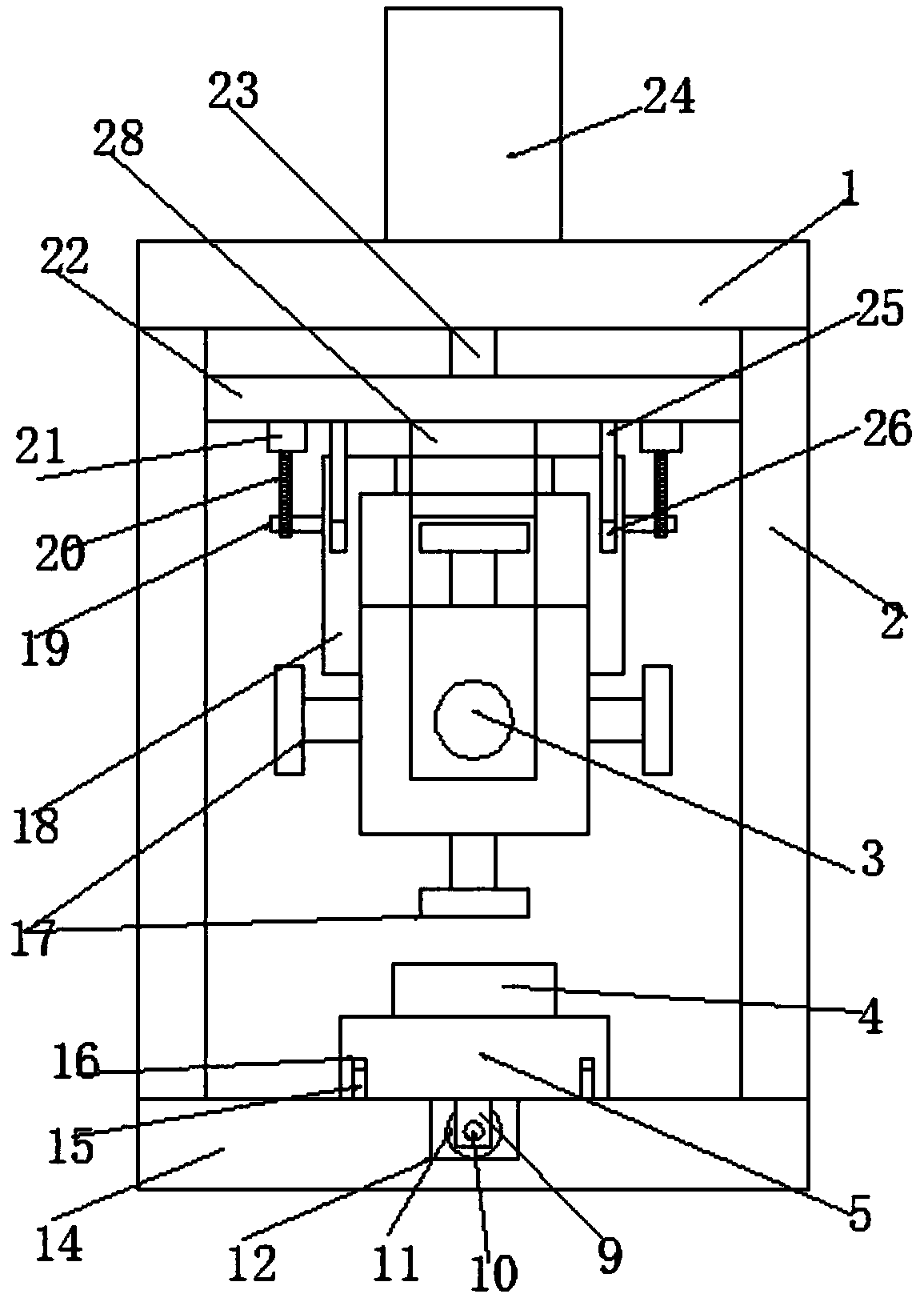
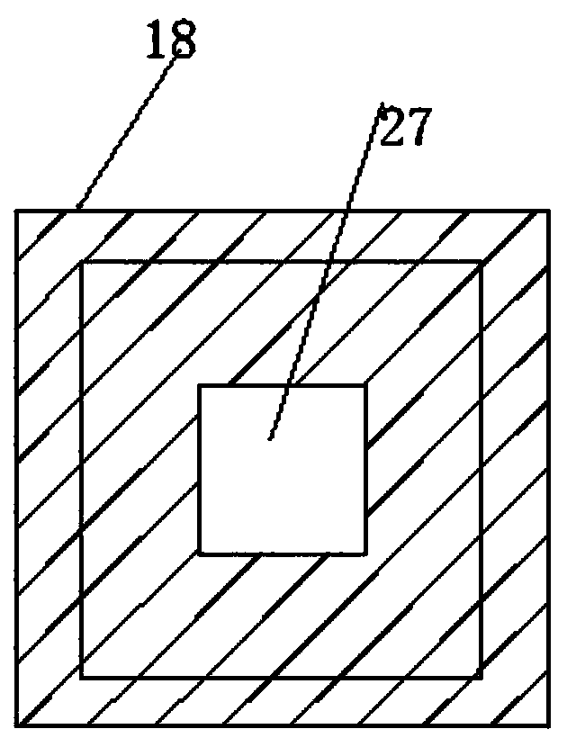
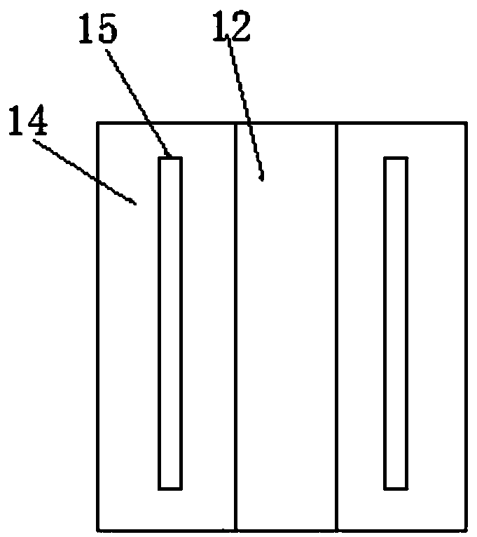
[0023] see Figure 1~4 , in an embodiment of the present invention, a punching machine for bolt processing includes a mounting plate 1 and a processing seat 14, a base 14 is provided under the mounting plate 1, and the support plate 2 and the mounting plate 1 are connected by the support plate 2 on both sides of the upper end of the base 14. The connection is fixed, the middle position of the upper end of the installation plate 1 is provided with a driving hydraulic cylinder 24, the output end of the driving hydraulic cylinder 24 is provided with an output rod 23, and the lower end of the output rod 23 is connected to the lifting slide plate 22, and the left and right ends of the lifting slide plate 22 are connected to the two sides. The support plate 2 is in sliding contact, and the support plate 2 is provided with a lifting chute matched with the lifting slide plate 22. The lower end of the lifting slide plate is symmetrically provided with two hanging plates 28, and a rotati...

Embodiment 2

[0029] see Figure 5 , and the difference from Embodiment 1 is: the buffer seat 13 is provided under the processing seat 14, the support sleeve 7 is symmetrically provided on both sides of the upper end of the buffer seat 13, and the upper end of the support sleeve 7 is slidingly provided with a support leg 6, and the upper end of the support leg 6 is It is connected and fixed with the processing seat 14, and is also connected and fixed by several buffer springs 8 between the buffer seat 13 and the processing seat 14. The setting of this buffer mechanism reduces the impact on the ground when the device is working.


PUM


Abstract

The invention discloses a punching machine for bolt machining. The punching machine comprises a mounting plate and a machining seat. A base is arranged below the mounting plate. The two sides of the upper end of the base and the mounting plate are connected and fixed through supporting plates. A drive hydraulic cylinder is arranged in the middle of the upper end of the mounting plate. An output rod is arranged at the output end of the drive hydraulic cylinder. The lower end of the output rod is connected with a lifting sliding plate. The left end and the right end of the lifting sliding plateare in sliding contact with the supporting plates on the two sides. Two hanging plates are symmetrically arranged at the lower end of the lifting sliding plate. A rotating shaft is arranged between the hanging plates. The rotating shaft is rotationally provided with a rotating switching block. The punching machine is simple and reasonable in structure, by arranging a punch capable of being rotatedand switched and a lower mold capable of being replaced, machining on different bolts can be achieved by replacing a movable block, thus the defects of an existing device are overcome, and practicability is high.

Description

technical field [0001] The invention relates to the technical field of mechanical processing equipment, in particular to a punching machine for bolt processing. Background technique [0002] In the field of bolt processing, it is necessary to use a punching machine to stamp and form bolts. The working process when processing the bolt head of the bolt is: the worker uses the pliers to place the cylindrical workpiece whose top has been heated to the red state into the die, and the punching head of the stamping mechanism falls to punch the workpiece to form a hexagonal bolt head or round head. Bolts, after the stamping is completed, the punching head rises, and the formed product is clamped out. The defect of the present punching machine is that the die is fixedly arranged on the workbench of the punching machine, and the die is not easy to replace, which leads to a single type of bolt punched by the punching machine, and each punching machine is only suitable for punching one...

Claims


Application Information

Patent Timeline
Patent Type & Authority Applications(China)
IPC IPC(8): B21D37/06B21D53/24
CPCB21D37/06B21D53/24
Inventor 王立新
Owner ANHUI LIUFANG ZHONGLIAN MECHANICAL SHARE
Why Eureka
Try Eureka