Flow control method and device for zinc liquid in hot galvanizing zinc pot

A flow control and hot-dip galvanizing technology, which is applied to the surface coating liquid device, hot-dip galvanizing process, coating, etc., to prevent the consumption of zinc resources, reduce manual operations, and avoid accumulation and agglomeration

Active Publication Date: 2018-12-14
BAOSHAN IRON & STEEL CO LTD
View PDF9 Cites 3 Cited by
  • Summary
  • Abstract
  • Description
  • Claims
  • Application Information

AI Technical Summary

Problems solved by technology

However, this patent is mainly aimed at circular molten iron ladles. The arrangement of the traveling wave magnetic field and the control of the direction of the magnetic field are relatively simple, and it must cooperate with the slag tank to work normally. Consider the impact of molten iron flow on product quality

Method used


Image

  • Flow control method and device for zinc liquid in hot galvanizing zinc pot
  • Flow control method and device for zinc liquid in hot galvanizing zinc pot
  • Flow control method and device for zinc liquid in hot galvanizing zinc pot

Examples


Embodiment 1

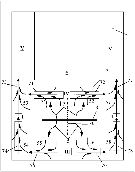
[0038] see figure 2 A total of 8 sections of traveling wave magnetic field generators are installed on the left and right sides of the zinc pot 1 hot-dip area (area I and area II), the front end (area III) and the position between the strip steel 3 and the furnace nose 4 (area IV). Respectively: the first left segment traveling wave magnetic field generator 73, the second left segment traveling wave magnetic field generator 74, the first right segment traveling wave magnetic field generator 77, the second right segment traveling wave magnetic field generator 78, the first front segment traveling wave magnetic field generator 75, the first Two rear traveling wave magnetic field generators 76 , a first rear traveling wave magnetic field generator 71 , and a second rear traveling wave magnetic field generator 72 .

[0039] The first left segment traveling wave magnetic field generator 73, the second left segment traveling wave magnetic field generator 74, the first front segment...

Embodiment 2

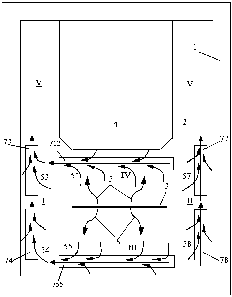
[0047] see image 3 , the transversely arranged traveling wave magnetic field generator located at the front end of the zinc pot (Zone III) and the position between the strip steel and the furnace nose (Zone IV) is a full-length type, that is, the front traveling wave magnetic field generator 756 and the rear traveling wave magnetic field generator 756 Magnetic field generator 712, and the direction of the traveling wave magnetic field excited by the whole length type traveling wave magnetic field generator is in the same direction, so as to drive the zinc liquid to flow to a certain side of the zinc pot, and generate The liquid zinc flow is connected, and the liquid zinc driven by the transverse traveling wave magnetic field generator is turned and driven to the rear end of the zinc pot (V zone).

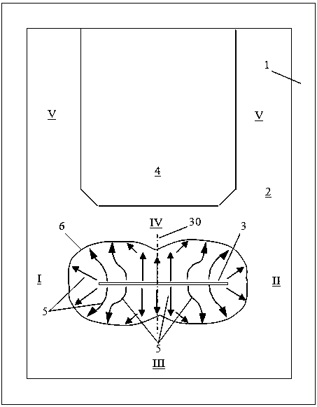
[0048] Depend on figure 1 It can be seen that in the prior art, under the blowing action of the air knife, the liquid zinc flows obliquely along the center line of the strip to bo...


PUM


Abstract

The invention discloses a flow control method and device for zinc liquid in a hot galvanizing zinc pot. The control method disclosed by the invention comprises the following steps: promoting zinc liquid (2) to respectively outwards diffuse and flow towards areas (I, II, III and IV) formed among the left side, right side and front end of the zinc pot, strip steel and a furnace nose (4) by virtue ofthe blowing effect of an air knife above the hot galvanizing zinc pot (1) on the strip steel (3), and dragging top ballast which is rapidly produced on the surface of the zinc liquid to outwards flowtowards the area; arranging multistage traveling wave magnetic field generators (71, 72, 73, 74, 75, 76, 77 and 78) above the surface of the zinc liquid in the zinc pot on the edge sides of the areasso as to excite the traveling wave magnetic field to generate electromagnetic propulsion on the zinc liquid so as to drive the zinc liquid to flow, mutually linking the zinc liquid flow caused by thetraveling wave magnetic field generators with blowing flow of the air knife, and promoting the zinc liquid on the surface of the zinc pot to orderly flow towards the rear end (the Vth area) of the zinc pot; dragging the top ballast floating on the surface of the zinc liquid to flow according to the control direction by the flowing zinc liquid.

Description

technical field [0001] The invention relates to the technical field of hot-dip galvanizing, in particular to a method and device for controlling the flow of zinc liquid in a hot-dip galvanizing pot. Background technique [0002] As we all know, the hot-dip galvanizing process is completed by the strip steel passing through the zinc pot. Among them, the strip steel entering the zinc pot at high speed, the movement of the sinking roller assembly in the zinc pot, and the blowing action of the air knife will inevitably cause the flow of zinc liquid. At the same time, the zinc liquid and aluminum components in the zinc pot are particularly active at high temperatures (about 450°C, and the temperature of the aluminum plating pot is as high as 650°C), and have complex chemical reactions with the Fe elements brought in by the strip steel to form Zn -Fe-Al ternary metal compounds, etc., namely zinc slag, zinc slag can be divided into surface slag (also known as scum), suspended slag ...

Claims


Application Information

Patent Timeline
Patent Type & Authority Applications(China)
IPC IPC(8): C23C2/06
CPCC23C2/06C23C2/00C23C2/0034C23C2/40C23C2/325C23C2/50C23C2/0035B05C3/02
Inventor 侯晓光钱洪卫于雷李山青陆勇金鑫焱周月明
Owner BAOSHAN IRON & STEEL CO LTD
Why Eureka
Try Eureka