Cooling structure of turbine outer shell flange based on micro-electronics technology

A microelectronic technology and cooling structure technology, applied in the field of steam turbine cooling, can solve problems such as low work efficiency, large waste of equipment exhaust gas capacity, and poor cooling capacity of the casing

Inactive Publication Date: 2018-12-14
张莉笛
View PDF0 Cites 1 Cited by
  • Summary
  • Abstract
  • Description
  • Claims
  • Application Information

AI Technical Summary

Problems solved by technology

[0002] At present, with the advancement of science and technology and the development of society, steam turbines are used more and more widely, and the demand for steam turbines is increasing. The cooling capacity of the existing steam turbine shell is poor, and it is difficult to cool down quickly after the equipment stops, and it is easy to generate steam. Leakage, often condensed water inside the equipment is difficult to deal with, and the exhaust gas capacity of the equipment is wasted, resulting in energy waste and low work efficiency

Method used


Image

  • Cooling structure of turbine outer shell flange based on micro-electronics technology
  • Cooling structure of turbine outer shell flange based on micro-electronics technology

Examples


Embodiment Construction

[0011] The following will clearly and completely describe the technical solutions in the embodiments of the present invention with reference to the accompanying drawings in the embodiments of the present invention. Obviously, the described embodiments are only some, not all, embodiments of the present invention. Based on the embodiments of the present invention, all other embodiments obtained by persons of ordinary skill in the art without making creative efforts belong to the protection scope of the present invention.

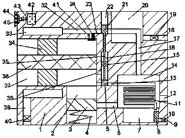
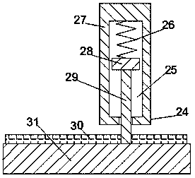
[0012] see Figure 1-2, an embodiment provided by the present invention: a cooling structure for the flange of a steam turbine shell based on microelectronic technology, including a steam turbine shell 1, and a turbine space 37 whose left end wall communicates with the external space is arranged inside the steam turbine shell 1, and the The turbine space 37 is provided with a rotating shaft 36 whose two ends are respectively rotatably connected to the left and...


PUM


Abstract

The invention discloses a cooling structure of a turbine outer shell flange based on a micro-electronics technology. The cooling structure comprises a turbine outer shell, the turbine outer shell is internally provided with a turbine space which the left end wall communicates with the outside space, and a constant-pressure water storage space which the upper end wall communicates with the turbinespace is formed in the right inner side of the lower end wall of the turbine space; and a cooling space is formed in the right inner end wall of the constant-pressure water storage space, an exhaust pipeline which the right end wall communicates with the outside space is arranged in the lower inner side of the right end of the cooling space, and a translation space which the lower end wall communicates with a steam pipeline is formed in the right inner end wall of the turbine space. According to the structure, when in use, the device has the advantages that the mechanism is simple, the operation is convenient, and the flange of the turbine outer shell can be continuously cooled, moreover, the equipment can be rapidly cooled after the working is stopped, the possibility of steam leakage isreduced, and the residual problem of the steam tail gas residual can be well treated; and the problem of condensation inside the equipment is solved, the energy generated by the equipment is reasonably utilized, so that the energy loss is effectively reduced, and then the working efficiency is improved.

Description

technical field [0001] The invention relates to the field of steam turbine cooling, in particular to a cooling structure for a flange of a casing of a steam turbine based on microelectronic technology. Background technique [0002] At present, with the advancement of science and technology and the development of society, steam turbines are used more and more widely, and the demand for steam turbines is increasing. The cooling capacity of the existing steam turbine casing is poor, and it is difficult to cool down quickly after the equipment stops, and it is easy to generate steam. Leakage, often condensed water inside the equipment is difficult to deal with, and the exhaust gas capacity of the equipment is wasted, resulting in energy waste and low work efficiency. Contents of the invention [0003] The object of the present invention is to provide a cooling structure for the casing flange of a steam turbine based on microelectronic technology, so as to solve the problems ra...

Claims


Application Information

Patent Timeline
Patent Type & Authority Applications(China)
IPC IPC(8): F01D25/12F01K11/02F01K19/10
CPCF01D25/12F01K11/02F01K19/10
Inventor 张莉笛
Owner 张莉笛
Why Eureka
Try Eureka