L-shaped shearing seepage experiment device applicable to joint or fractured rock mass and method of L-shaped shearing seepage experiment device

An experimental device and joint technology, applied in the direction of using a stable shear force to test material strength, measurement device, permeability/surface area analysis, etc., can solve problems such as not well adapted to shear modules and not necessarily temperature control. , to avoid friction and improve measurement accuracy

Active Publication Date: 2018-12-14
INST OF ROCK & SOIL MECHANICS CHINESE ACAD OF SCI
View PDF8 Cites 11 Cited by
  • Summary
  • Abstract
  • Description
  • Claims
  • Application Information

AI Technical Summary

Problems solved by technology

Although these devices and methods can solve the problem of fluid sealing and radial measurement, they cannot independently complete the shear seepage experiment of joints, and need to rely on other equipment, such as conventional triaxial testing machines
Moreover, the loading control methods of these external devices are not well adapted to the shear module, and may not be able to achieve temperature control

Method used


Image

  • L-shaped shearing seepage experiment device applicable to joint or fractured rock mass and method of L-shaped shearing seepage experiment device
  • L-shaped shearing seepage experiment device applicable to joint or fractured rock mass and method of L-shaped shearing seepage experiment device
  • L-shaped shearing seepage experiment device applicable to joint or fractured rock mass and method of L-shaped shearing seepage experiment device

Examples


Embodiment Construction

[0057] Below in conjunction with accompanying drawing and embodiment describe in detail:

[0058] 1. Device

[0059] 1. Overall

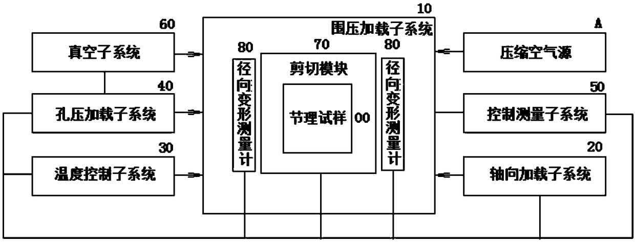
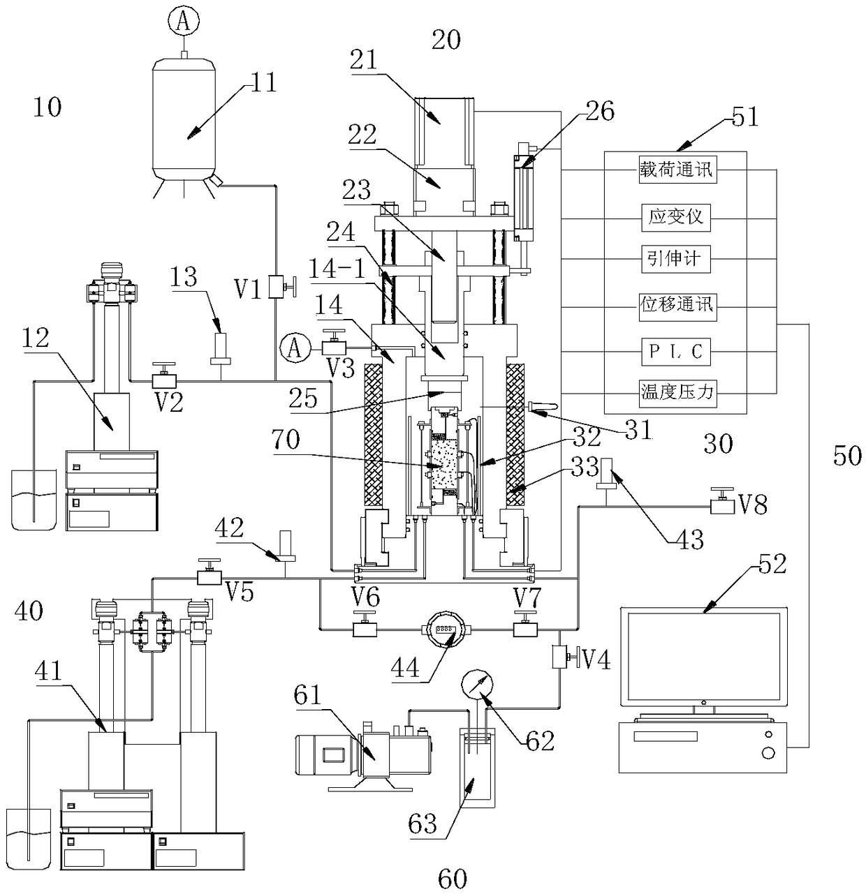
[0060] Such as figure 1 , the device includes the experimental object - joint sample 00; it is equipped with 6 subsystems and other components;

[0061] The six subsystems include confining pressure loading subsystem 10, axial loading subsystem 20, temperature control subsystem 30, pore pressure loading subsystem 40, control and measurement subsystem 50 and vacuum subsystem 60;

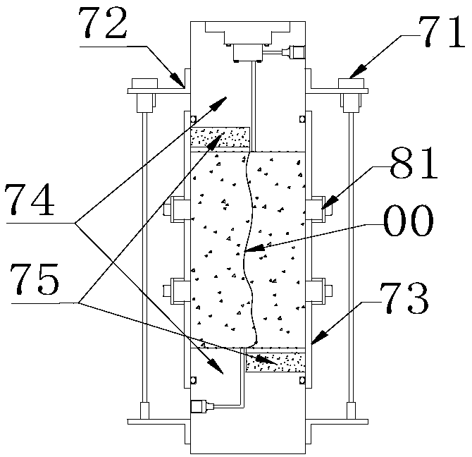
[0062] Other components include a shear module 70, a radial deformation gauge 80, a compressed air source A and the first, second...8 valves V1, V2...V8;

[0063] Its location and connection relationship are:

[0064] The joint sample 00 is placed in the shear module 70, the shear module 70 is placed in the confining pressure loading subsystem 10, and the radial deformation measuring gauge 80 is clamped on both sides of the joint sample 00;

[0065] The confining press...


PUM


Abstract

The invention discloses an L-shaped shearing seepage experiment device applicable to a joint or fractured rock mass and a method of the L-shaped shearing seepage experiment device and relates to rockmechanic experiment techniques. According to the device, a joint test sample is placed in a shearing module, and the shearing module is arranged in a confining pressure loading subsystem; a radial deformation measuring meter is arranged on both sides of the joint test sample in a clamping manner; the confining pressure loading subsystem is connected with a compressed air source through a pipelineand a valve; an axial loading subsystem, a pore pressure loading subsystem, a temperature control subsystem, a control measuring subsystem and a vacuum subsystem are respectively connected with the confining pressure loading subsystem. By adopting the device, shearing seepage experiments under the action of high temperatures and high pore pressure can be completed, and the seepage of a joint in shearing can be also measured; due to adoption of a servo motor and a precise bead screw rod, high-precision control on axial displacement can be achieved, and the device can be operated stably for a long time; due to adoption of an underwater load sensor, the friction of a confining pressure chamber piston can be avoided, and the stress measurement precision can be improved.

Description

technical field [0001] The invention relates to rock mechanics test technology, in particular to an L-shaped shear seepage test device and method suitable for jointed or fissured rock masses. Background technique [0002] The mechanical and hydraulic properties of rock mass depend largely on the mechanical and hydraulic properties of joints or fractures in rock mass, and shear seepage experiments on joints or fractures are an important means to study these properties. However, the existing shear seepage equipment cannot meet the research needs of the mechanical and hydraulic characteristics of deep-buried joints. Because the deep rock mass is in an environment of high temperature and high pore pressure, the study of the mechanical and hydraulic properties of deeply buried joints needs to simulate the environment of high temperature and high pore pressure. The existing shear seepage equipment is only suitable for shear seepage experiments under the action of low pore pressur...

Claims


Application Information

Patent Timeline
Patent Type & Authority Applications(China)
IPC IPC(8): G01N3/24G01N15/08
CPCG01N3/24G01N15/088
Inventor 李小春张强方志明
Owner INST OF ROCK & SOIL MECHANICS CHINESE ACAD OF SCI
Why Eureka
Try Eureka