Composite material lamination beam layered damage position detection method

A composite material layer, damage location technology, applied in material inspection products, analytical materials, measuring devices, etc., can solve problems such as difficulty in meeting, and achieve the effect of simple operation

Active Publication Date: 2018-12-14
HOHAI UNIV
View PDF8 Cites 10 Cited by
  • Summary
  • Abstract
  • Description
  • Claims
  • Application Information

AI Technical Summary

Problems solved by technology

However, these methods generally need to predict the approximate location of the delamination damage, and the location of the delamination damage must be easily accessible, which is difficult to meet in practical applications.
However, bas

Method used


Image

  • Composite material lamination beam layered damage position detection method
  • Composite material lamination beam layered damage position detection method
  • Composite material lamination beam layered damage position detection method

Examples


Embodiment Construction

[0042] Below in conjunction with accompanying drawing, technical scheme of the present invention is described in further detail:

[0043] Those skilled in the art can understand that, unless otherwise defined, all terms (including technical terms and scientific terms) used herein have the same meaning as commonly understood by one of ordinary skill in the art to which this invention belongs.

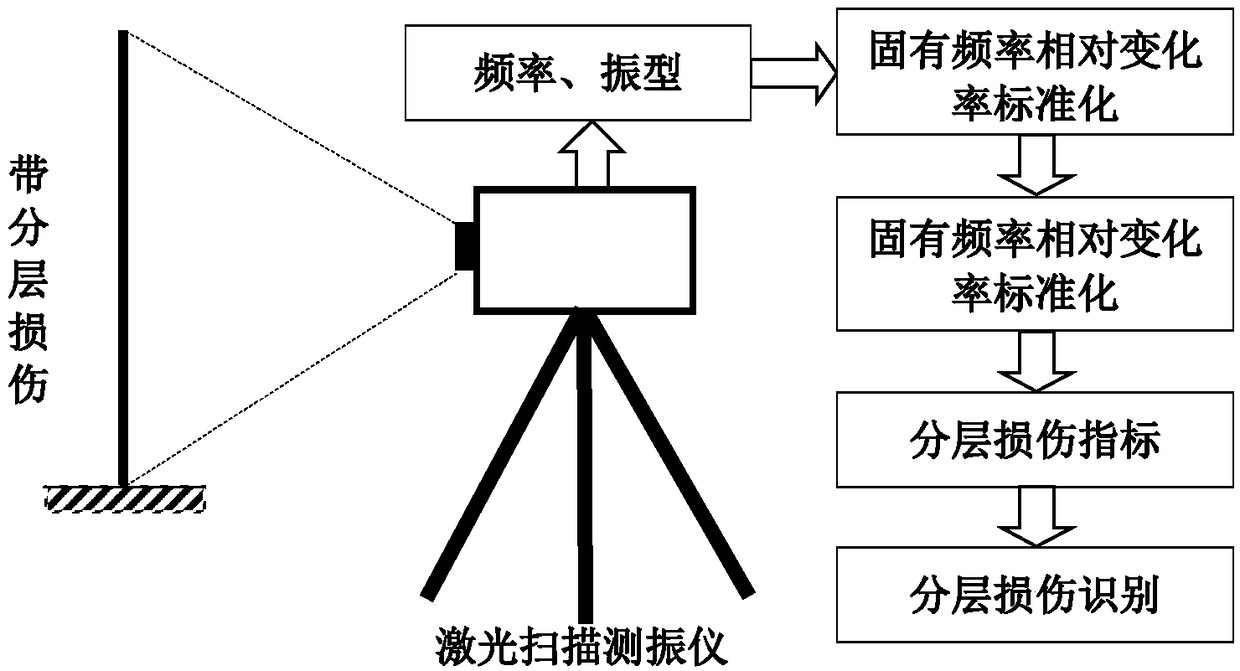
[0044] Such as figure 1 As shown, a method for detecting the delamination damage position of a composite material laminated beam proposed by the present invention comprises the following steps:

[0045] 1. Measure the natural frequency ω of the first m (m ≥ 5) layers of composite laminated beams before and after damage j , Calculate the relative rate of change of the natural frequency and standardize it as [01] interval:

[0046]

[0047]

[0048] Among them, j∈{1,2,...,m} is the frequency order, Δω j Represents the relative rate of change of the jth order natural frequency, δ...


PUM


Abstract

The invention discloses a composite material lamination beam layered damage position detection method. The method comprises the following steps of measuring the inherent frequency before and after a first 10-order damage of the composite material lamination beam and the vibration type after damage; calculating the relative change rate of the inherent frequency, and standardizing the relative change rate of the inherent frequency; calculating the square of the first-order derivative of the vibration type, and performing standardization on the square; according to the standard inherent frequencyrelative change rate and the standard square of the first-order derivative of the vibration type, calculating first 10-order single-order layered damage indexes, and performing multiple multiplication on the first 10-order single-order layered damage indexes to obtain an overall layered damage index; and determining the layered damage position according to the position of the maximum value of theoverall layered damage index. The method can be used for analyzing the inherent frequency before and after layered damage of the composite material lamination beam and the vibration type after damage, so as to judge the layered damage position.

Description

technical field [0001] The invention discloses a method for detecting the delamination damage position of a composite material laminated beam, and specifically relates to the technical field of composite material laminated beam structural damage detection. Background technique [0002] Composite laminated beam structures are vulnerable to impact and cause fine delamination damage during long-term service. These subtle layered damages will accumulate and evolve into macroscopic damages that endanger the safe and reliable operation of the overall structure. Based on this, various nondestructive testing methods have developed rapidly in recent years, and local nondestructive testing methods such as ultrasonic, electromagnetic field, and eddy current have been widely used in the delamination damage detection of composite laminated beams. However, these methods generally need to predict the approximate location of the delamination damage, and the location of the delamination dam...

Claims


Application Information

Patent Timeline
IPC IPC(8): G01N33/00
CPCG01N33/00G01N2033/0003G01N2033/0078
Inventor 曹茂森沙刚刚
Owner HOHAI UNIV
Why Eureka
Try Eureka