Eureka AIR delivers breakthrough ideas for toughest innovation challenges, trusted by R&D personnel around the world.

Radar target detection method combined with time domain and spatial domain on basis of feed network

A feeding network and radar target technology, which is applied in the field of radar target detection combined with time domain and space domain, can solve the problems of large beam coverage and difficulty in long-distance detection, and achieve the effect of accurately identifying target point information

Active Publication Date: 2018-12-14
UNIV OF ELECTRONIC SCI & TECH OF CHINA
View PDF6 Cites 2 Cited by
  • Summary
  • Abstract
  • Description
  • Claims
  • Application Information

AI Technical Summary

Problems solved by technology

However, these two algorithms have their own shortcomings: in the target recognition of the time domain, a large number of antennas and feed networks are needed as the basis to accurately locate the target point; the target recognition of the algorithm in the space domain is due to the The coverage is relatively large, because it is difficult to achieve long-distance detection

Method used


Image

  • Radar target detection method combined with time domain and spatial domain on basis of feed network
  • Radar target detection method combined with time domain and spatial domain on basis of feed network
  • Radar target detection method combined with time domain and spatial domain on basis of feed network

Examples


Embodiment Construction

[0036] In order to understand the above-mentioned purpose, features and advantages of the present invention more clearly, the present invention will be further described in detail below in conjunction with the accompanying drawings and specific embodiments. It should be noted that, under the condition of not conflicting with each other, the embodiments of the present application and the features in the embodiments can be combined with each other.

[0037] In the following description, many specific details are set forth in order to fully understand the present invention. However, the present invention can also be implemented in other ways different from the scope of this description. Therefore, the protection scope of the present invention is not limited by the following disclosure. limitations of specific examples.

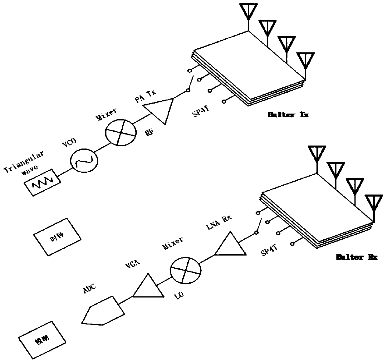
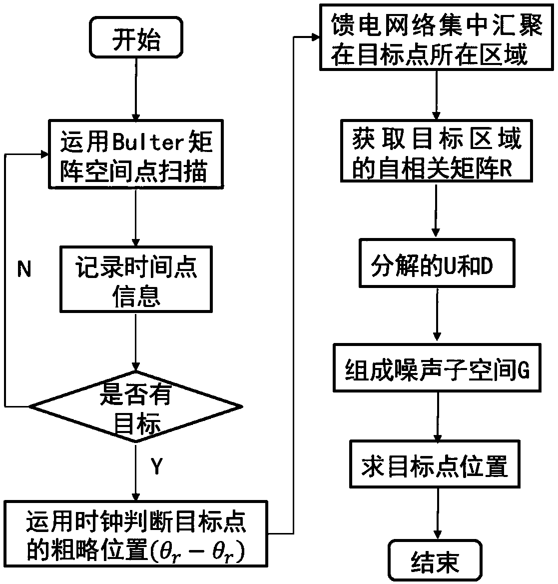
[0038] Please refer to Figure 1-Figure 2 , the antenna network is used to receive the target signal, and the algorithm is used to process the signal to obtain ...


PUM


Abstract

The invention discloses a radar target detection method combined with a time domain and a spatial domain on basis of a feed network. The method comprises the following steps: utilizing the time characteristic of the feed network to explore a general orientation of a target point in the space; using the time signal to acquire a coarse position of the target point position; focusing on the antenna signal; and acquiring specific position information of the target point by using the phase relation between the received signals and a subspace decomposition algorithm. According to the radar target detection method combined with a time domain and a spatial domain on basis of a feed network in the invention, a bulter feed network is used for achieving beam scanning at the time domain stage; compared with one beam, the beamforming detection distance is further away in a fixed specific direction; the spatial domain stage scanned by using the algorithm is realized by using an algorithm; more target points can be positioned within an angle range; and the target point information can be identified more accurately.

Description

technical field [0001] The field of radar target detection of the present invention, in particular, relates to a radar target detection method based on the combination of time domain and space domain of a feeding network. Background technique [0002] Self-driving vehicles (Autonomous vehicles; Self-piloting automobile), also known as unmanned vehicles, computer-driven vehicles, or wheeled mobile robots, are intelligent vehicles that realize unmanned driving through computer systems. It has a history of several decades in the 20th century, and it has shown a trend close to practicality in the early 21st century. Although the current self-driving vehicles have not yet reached the level of fully autonomous driving, self-driving vehicles will become the mainstream development direction of future vehicles, as this point of view has been widely recognized in the industry. At present, the development of unmanned driving technology has made great progress, but it is still in the e...

Claims


Application Information

Patent Timeline
IPC IPC(8): G01S7/292
CPCG01S7/2923
Inventor 马凯学赵俊炎王勇强
Owner UNIV OF ELECTRONIC SCI & TECH OF CHINA
Why Eureka
Eureka Blog
Learn More