Concrete structure repair detection method and system, apparatus and storage medium

A concrete structure and detection method technology, which is applied in the field of concrete structure repair detection and computer-readable storage media, can solve the problem of unfavorable data recording and storage, intuitive analysis of conductive cloud images, labor and equipment costs, and difficulty in comprehensively measuring multi-point resistance. Value and other issues, to achieve the effect of saving labor costs, avoiding manual readings, and realizing intelligent operation

Inactive Publication Date: 2018-12-14
GUANGDONG UNIV OF TECH
View PDF7 Cites 0 Cited by
  • Summary
  • Abstract
  • Description
  • Claims
  • Application Information

AI Technical Summary

Problems solved by technology

Most of the existing technologies use analog or digital three-purpose ammeters, or measure with indirect voltammetry to obtain resistance values. These measurement methods are still sufficient when dealing with single points or a small number of points, but To be applied to large-area concrete conductivity measurement, in order to improve efficiency and speed, only the investment of instruments and manpower has to be increased. In addition to the lengthy measurement time, it also requires expensive manpower and equipment costs, causing users to be in the actual situation. In terms of measurement, for the sake of time and cost, usually only some of the points to be measured are selected, and it is difficult to comprehensively measure the multi-point resistance value, so it is easy to produce deviations that affect judgment and increase the risk of rework
In addition, previous measurement methods such as digital electric meters required manual reading, which would easily cause human error factors, and was not conducive to data recording and storage and subsequent intuitive analysis of conductivity cloud images, hindering the further improvement of work efficiency

Method used


Image

  • Concrete structure repair detection method and system, apparatus and storage medium
  • Concrete structure repair detection method and system, apparatus and storage medium
  • Concrete structure repair detection method and system, apparatus and storage medium

Examples


Embodiment Construction

[0038] The following will clearly and completely describe the technical solutions in the embodiments of the present invention with reference to the accompanying drawings in the embodiments of the present invention. Obviously, the described embodiments are only some, not all, embodiments of the present invention. Based on the embodiments of the present invention, all other embodiments obtained by persons of ordinary skill in the art without creative efforts fall within the protection scope of the present invention.

[0039] The embodiment of the invention discloses a concrete structure repair detection method, which improves the repair detection efficiency of the concrete structure.

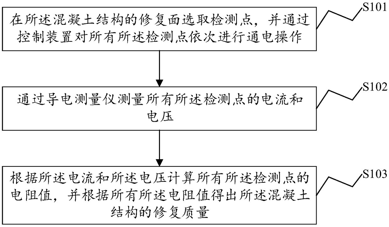
[0040] see figure 1 , a flow chart of a concrete structure repair detection method disclosed in an embodiment of the present invention, such as figure 1 shown, including:

[0041] S101: selecting detection points on the repaired surface of the concrete structure, and sequentially electrifying al...


PUM


Abstract

The invention discloses a concrete structure repair detection method and system, an apparatus and a computer-readable storage medium. The method comprises the following steps: selecting detection points on the repair surface of the concrete structure, and sequentially electrifying all the detection points through a control device; measuring currents and voltages at all said detection points by means of a conductivity gauge; calculating a resistance value of the detection point according to the current and the voltage, and obtaining a repair quality of the concrete structure according to all the resistance values. The invention provides a concrete structure repair detection method, which uses an electric conductivity measuring instrument to replace a three-power meter to achieve the purposeof automatically measuring the resistance value, avoiding manual reading, saving the expenditure of human cost, and realizing intelligent operation. In a very short period of time, the resistance value of several points on the damaged concrete surface is measured, which is comprehensive and fast, and greatly improves the work efficiency of measurement.

Description

technical field [0001] The present invention relates to the field of construction, and more specifically, to a concrete structure repair detection method, system and equipment, and a computer-readable storage medium. Background technique [0002] In the process of repairing and detecting concrete structures, it is necessary to obtain the resistance values ​​of multiple detection points on the repaired surface. Most of the existing technologies use analog or digital three-purpose ammeters, or measure with indirect voltammetry to obtain resistance values. These measurement methods are still sufficient when dealing with single points or a small number of points, but To be applied in large-area concrete conductivity measurement, in order to improve efficiency and speed, only the investment of instruments and manpower has to be increased. In addition to the lengthy measurement time, it also requires expensive manpower and equipment costs, causing users to be in the actual situati...

Claims


Application Information

Patent Timeline
Patent Type & Authority Applications(China)
IPC IPC(8): G06Q10/06G06Q50/08
CPCG06Q10/06395G06Q50/08
Inventor 汪毅叶洲健黎晓达邓军
Owner GUANGDONG UNIV OF TECH
Why Eureka
Try Eureka