Display panel and manufacturing method thereof

A technology for display panels and manufacturing methods, which is applied to semiconductor devices, electrical components, circuits, etc., can solve the problems of difficult control of the transfer process, reduced production costs, and small size of the products, so as to achieve simple and easy control of the transfer process, reduce production costs, Flexible and convenient control

Active Publication Date: 2018-12-14
SHANGHAI TIANMA MICRO ELECTRONICS CO LTD
View PDF9 Cites 14 Cited by
  • Summary
  • Abstract
  • Description
  • Claims
  • Application Information

AI Technical Summary

Problems solved by technology

[0003] After the light-emitting diode is manufactured, it needs to be transferred to the driving circuit board. Due to its small size and the large number of transfers, it is obviously impractical to use manual transfer.
At present, the commonly used transfer method is to make a special transfer head. The transfer head mainly uses electrostatic force, van der Waals force, etc. to pick up multiple light-emitting diodes at one time, and then transfers them to the drive substrate. However, the structure of the transfer head is relatively complicated and difficult to manufacture. The process is not easy to control, and it is not conducive to the reduction of product production costs, and when making large-scale display products, the work efficiency is very low

Method used


Image

  • Display panel and manufacturing method thereof
  • Display panel and manufacturing method thereof
  • Display panel and manufacturing method thereof

Examples


Embodiment Construction

[0041] Various exemplary embodiments of the present invention will now be described in detail with reference to the accompanying drawings. It should be noted that the relative arrangements of components and steps, numerical expressions and numerical values ​​set forth in these embodiments do not limit the scope of the present invention unless specifically stated otherwise.

[0042] The following description of at least one exemplary embodiment is merely illustrative in nature and in no way taken as any limitation of the invention, its application or uses.

[0043] Techniques, methods and devices known to those of ordinary skill in the relevant art may not be discussed in detail, but where appropriate, such techniques, methods and devices should be considered part of the description.

[0044] In all examples shown and discussed herein, any specific values ​​should be construed as exemplary only, and not as limitations. Therefore, other instances of the exemplary embodiment may...


PUM


Abstract

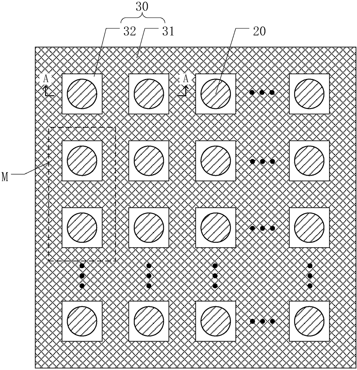
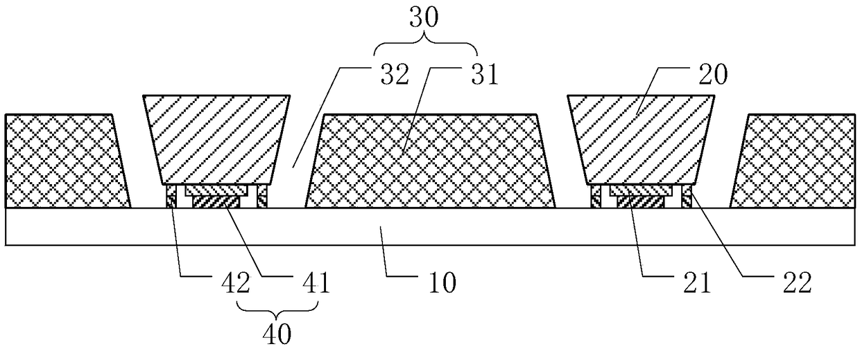
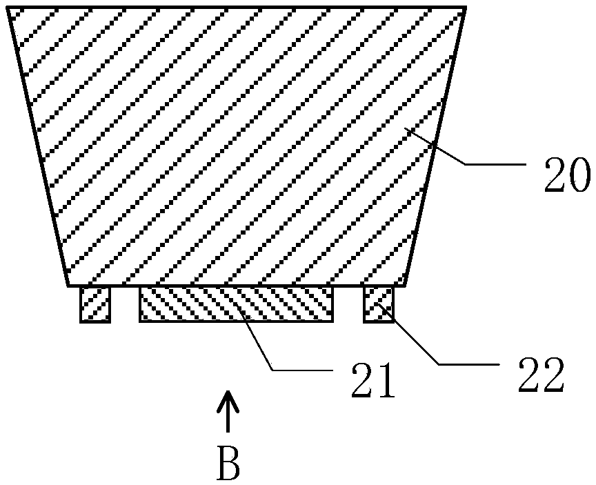
The invention discloses a display panel and a manufacturing method thereof, belonging to the technical field of display. The display panel comprises a driving substrate, a plurality of LED devices anda barrier layer and an electrode layer arranged on the driving substrate. The barrier layer comprises a barrier and a plurality of barrier openings arranged in an array, wherein the barrier openingsare separated by the barrier, and an LED device is arranged in one barrier opening; The LED device includes a first electrode and a second electrode, the first electrode and the second electrode are located on the same side of the LED device, and the second electrode is disposed around the first electrode; The electrode layer includes a ferromagnetic electrode and a lead wire positioned within thebaffle opening. Compared with the prior art, the assembly of the LED device on the driving substrate can be realized by energizing the lead wire, the transfer process is simple and easy to control, the efficiency is high, and the transfer head does not need to be made additionally, which is favorable for reducing the production cost of the product.

Description

technical field [0001] The present invention relates to the field of display technology, and more specifically, to a display panel and a manufacturing method thereof. Background technique [0002] Light Emitting Diode (LED for short) is a semiconductor diode that can convert electrical energy into light energy. Because of its small size (up to micron level), high brightness, low energy consumption, and long service life, it is widely used in display, lighting and other fields. [0003] After the light-emitting diode is manufactured, it needs to be transferred to the driving circuit board. Due to its small size and a large number of transfers, it is obviously impractical to use manual transfer. At present, the commonly used transfer method is to make a special transfer head. The transfer head mainly uses electrostatic force, van der Waals force, etc. to pick up multiple light-emitting diodes at one time, and then transfers them to the drive substrate. However, the structure ...

Claims


Application Information

Patent Timeline
Patent Type & Authority Applications(China)
IPC IPC(8): H01L25/075H01L33/36H01L33/38H01L33/40H01L33/48H01L33/62H01L33/00
CPCH01L25/0753H01L33/005H01L33/36H01L33/38H01L33/40H01L33/483H01L33/62H01L2933/0033H01L2933/0066
Inventor 何泽尚禹少荣
Owner SHANGHAI TIANMA MICRO ELECTRONICS CO LTD
Why Eureka
Try Eureka