Pipe fitting grooving machine and grooving processing technique for end of pipe fitting

A technology of rolling groove machine and pipe fittings, which is applied in metal processing, metal processing equipment, manufacturing tools, etc. It can solve the problems of easy scratches at the ends of pipe fittings and easy running of pipes, etc., to protect the touch screen, improve product quality, and improve processing efficiency. Effect

Pending Publication Date: 2018-12-18
浙江唯特利图伟管道设备有限公司
View PDF0 Cites 0 Cited by
  • Summary
  • Abstract
  • Description
  • Claims
  • Application Information

AI Technical Summary

Problems solved by technology

[0003] The object of the present invention is to provide a pipe fitting grooving machine and the grooving processing technology for the end of the pipe fittings, which mainly solves the problem that the existing pipe fitting grooving processing equipment and technology are easy to run when the existing pipe fitting grooving processing equipment and technology are grooving on pipe fittings such as tee elbows (i.e. : the pipe fitting breaks away from the knurling wheel), the d

Method used


Image

  • Pipe fitting grooving machine and grooving processing technique for end of pipe fitting
  • Pipe fitting grooving machine and grooving processing technique for end of pipe fitting
  • Pipe fitting grooving machine and grooving processing technique for end of pipe fitting

Examples


Embodiment Construction

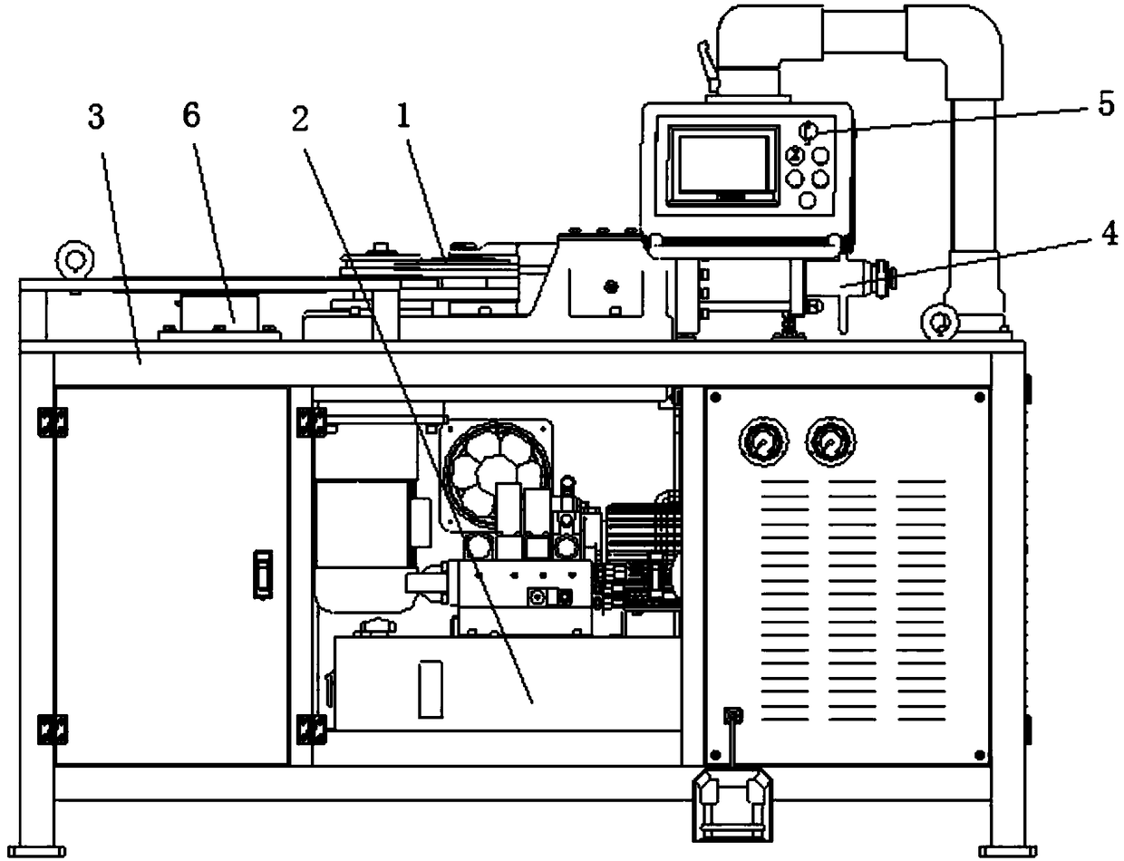
[0039] The invention discloses a pipe fitting rolling groove machine. see figure 2, which is a schematic view of the front structure of a preferred embodiment of the pipe fitting grooving machine of the present invention. As shown in the figure: it includes rolling grooving processing assembly 1, hydraulic assembly 2, frame 3, oil cylinder 4, touch screen assembly 5 and friction disc 6. The frame 3 has an operating platform and a supporting part located below the operating platform, and there is an accommodation space between the supporting parts under the operating platform. Wherein, the friction plate 6 is mainly arranged on the operating platform; the touch screen assembly 5 is arranged on the operating platform during use, and can be stored in the accommodation space after use; the oil cylinder 4 can be arranged on the operating platform; the hydraulic assembly 4 is mainly Set in the accommodation space; the rolling groove processing part of the rolling groove processin...


PUM


Abstract

The invention relates to a pipe fitting grooving machine and a grooving processing technique for the end of a pipe fitting. The pipe fitting grooving machine comprises a grooving processing assembly and a pressing wheel power component, wherein the grooving processing assembly comprises a main shaft, a motor, a knurling wheel, a pressing wheel shaft, a pressing wheel frame and a pressing wheel; the lower end of the main shaft is connected to the power output end of the motor; the upper end of the main shaft is provided with the knurling wheel; the pressing wheel is arranged on one side of theknurling wheel; the pressing wheel is connected to the pressing wheel frame through the pressing wheel shaft; and the pressing wheel frame is driven by the pressing wheel power component. The pipe fitting grooving machine and the grooving processing technique for the end of the pipe fitting solve the problems that the pipe fitting is prone to be detached from the knurling wheel in the grooving process on three-way elbows and other pipe fittings by existing pipe fitting grooving processing equipment and techniques, and that the end of the pipe fitting is prone to be scratched during processingbecause the variation of the distance from a groove to the end of the pipe fitting is great. The pipe fitting grooving machine and the grooving processing technique for the end of the pipe fitting arecapable of effectively controlling the variation of the distance from the groove to the end of the pipe fitting, improving the processing quality, and preventing the end of the pipe fitting from being scratched during processing. The pipe fitting grooving machine and the grooving processing technique for the end of the pipe fitting also have the advantages of precise and controllable groove processing depth of the pipe fitting, reasonable functional layout of equipment and the like, and are especially suitable for the grooving processing for the ends of special-shaped pipe fittings such elbows.

Description

technical field [0001] The invention relates to a device and a process for processing grooves on metal tubular products, in particular to a pipe fitting rolling groove machine and a rolling groove processing technology for the end of the pipe fittings. Background technique [0002] At present, during the laying of pipelines (such as steel pipes), pipe fittings such as tee elbows are often used when the pipeline path needs to be changed. These pipe fittings need to be connected by clamps, and the clamp connections need to be grooved on the ends of the pipe fittings. Although the current technology for rolling grooves on straight pipes is relatively mature, the current technology for rolling grooves on pipe fittings such as tee elbows is not perfect, such as figure 1 Shown: The problems usually encountered are the large variation of the distance A between the groove of width B and the end of the pipe fitting, and the end of the pipe fitting is easy to scratch during processing...

Claims


Application Information

Patent Timeline
IPC IPC(8): B21D17/04B21C51/00
CPCB21C51/00B21D17/04Y02P70/10
Inventor 杨岩顺张文仁
Owner 浙江唯特利图伟管道设备有限公司
Why Eureka
Try Eureka