Steam discharge in pulp or fiber refiners

A steam outlet, fiber separator technology, applied in pulp beating/refining method, fiber raw material, fiber raw material processing, etc. problem, to achieve the effect of uniform fiber quality, low specific energy consumption, and less micro-pulsation

Active Publication Date: 2020-11-27
VALMET OY
View PDF6 Cites 0 Cited by
  • Summary
  • Abstract
  • Description
  • Claims
  • Application Information

AI Technical Summary

Problems solved by technology

The steam flow through the refining space exhibits very high velocities and negatively affects the flow of fibrous material and also increases the energy consumption of the refiner
Steam can also flow in an irregular manner and thus affect the stability of the refining gap, making the material flow through the gap uneven

Method used


Image

  • Steam discharge in pulp or fiber refiners
  • Steam discharge in pulp or fiber refiners
  • Steam discharge in pulp or fiber refiners

Examples


Embodiment Construction

[0027] Throughout the drawings, the same reference numerals are used for similar or corresponding elements.

[0028] As mentioned in the background section, there is a continuing need in the art for further improvements in the removal of steam from the refining zone of a refiner.

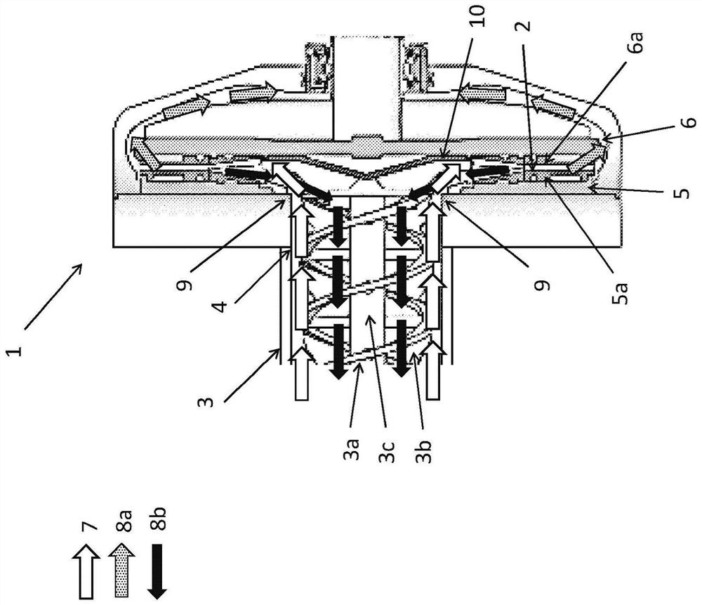
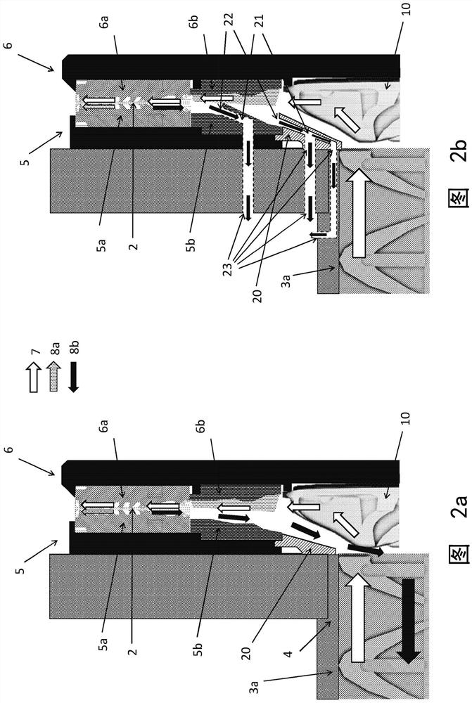
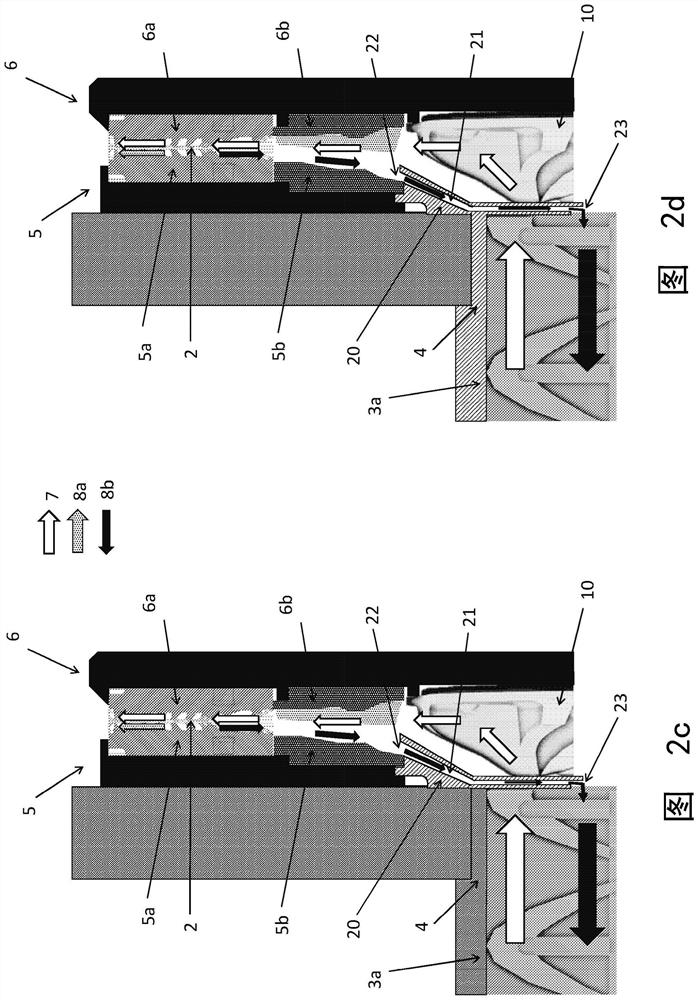
[0029] figure 1 is a schematic diagram of a typical defibrator arrangement in a pulp or fiber refiner. Here, a defibrator with a rotor and stator arrangement is described, but this embodiment can also be applied in a defibrator with two rotors. Lignocellulose-containing material 7, such as wood chips, is fed by a conveying screw / feed screw 3a, typically a belt feeder, via a feed channel 3 towards the defibrator 1 and through a material inlet opening 4 in the stator 5 into the refining disc, That is, the intermediate space between the stator 5 and the rotor 6 . The centrifugal force forces the material towards the periphery of the refining disc to emerge in the refining gap / space 2 between the ref...


PUM


Abstract

A first refining disc (5) of a defibrator (1) for refining fibrous material, adapted to receive feed from a feed screw (3a) through a material inlet opening (4) arranged in the first refining disc (5) ), the first refining disc (5) is provided with at least one steam discharge channel (21) comprising at least one steam inlet opening (22) and at least one steam outlet (23), the at least one steam inlet opening (22) is arranged on the side of the first refining disc (5) adapted to face the second refining disc (6), the at least one steam outlet (23) is arranged on the first On the side of the refining disc (5) which is adapted to face away from the second refining disc (6). The at least one steam outlet opening (23) is arranged centrally with respect to the center of the first refining disc (5) at the at least one steam inlet opening (22) and is centrally arranged with respect to the center of the first refining disc (5) at the inlet The material flow (7) is received from the feed screw (3a) into position in the first refining disc (5).

Description

technical field [0001] The present invention relates generally to the refining of fibrous material in pulp or fiber refiners, and in particular to the venting of steam generated during the refining process. Background technique [0002] A defibrator is a thermomechanical pulping refiner in which pulp material such as wood chips or other lignocellulose-containing fibrous material is ground in a steam environment between two refining discs, rotating grinding discs (rotors) with The fixed disks (stators) face each other, or alternatively, two rotating disks face each other to generate wood fibers. The refining discs are aligned along the pulp feed axis and the rotating disc is arranged on a rotatable axis which can be rotated relative to the other disc by means of eg an electric motor. The inner surfaces of the refining discs, ie the surfaces facing each other, are usually provided with one or more refining segments having refining bars and grooves of different sizes and orien...

Claims


Application Information

Patent Timeline
Patent Type & Authority Patents(China)
IPC IPC(8): D21D1/30B02C7/12D21B1/14
CPCD21D1/306D21D1/20B02C7/12D21B1/14
Inventor T·林德布罗姆
Owner VALMET OY
Why Eureka
Try Eureka