

Adjustable locating interference tool shank and adjusting method thereof
An adjustable and positioning knife technology, applied in positioning devices, accessories of tool holders, turning equipment, etc., can solve the problems of high labor cost and time cost, long time for grinding shims, and large number of adjustment shims, etc., to achieve Good adaptability, reduce labor intensity of workers, and improve installation efficiency
- Summary
- Abstract
- Description
- Claims
- Application Information
AI Technical Summary
Problems solved by technology
Method used
Image

Examples
Embodiment 1
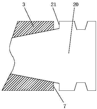
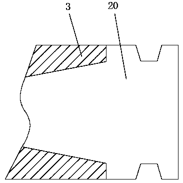
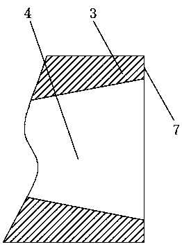
[0044] Such as Figures 3 to 8As shown, an adjustable over-positioning tool holder, the tool holder includes a conical part 1 and a cylindrical part 2, the outer diameter of the conical part 1 gradually increases from the back to the front, and the conical part 1 is used for fixed installation on the machine tool In the conical hole 4 at the front end of the main shaft 3, the rear end of the conical body 1 has an axial threaded hole (not shown in the figure), which is used for threaded connection with the pull stud (not shown in the figure), the main shaft 3 There is a pull claw (not shown in the figure), the pull claw grasps the pull nail, and both the pull claw and the pull nail are existing structures in the field, so that the knife handle can be tightened and fixed in the conical hole 4 at the front end of the main shaft 3, and the knife handle There are two positioning key grooves 17 on the top, and one end of the two positioning keys (not shown in the figure) on the main...
Embodiment 2
[0047] Such as Figures 6 to 8 As shown, on the basis of Embodiment 1, the front end of the adjusting ring one 6 has an inner cone surface 11, and the rear end of the adjusting ring two 9 has an outer cone surface 12, and the outer cone surface 12 is used to fit and tighten the inner cone surface 11 , and matched, the outer conical surface 12 is ring-shaped, and the inner conical surface 11 is composed of two arc-shaped segments, and the two arc-shaped segments are divided into two notches 18 on the adjusting ring one 6 .
Embodiment 3
[0049] On the basis of embodiment 2, the adjustment section 5 is connected to the front end of the cone part 1, and the diameter of the adjustment section 5 is not less than the maximum diameter of the front end of the cone part 1, and the diameter of the adjustment section 5 is less than or equal to the minor diameter of the external thread 8, The diameter of the imaginary cylinder tangent to the bottom of the external thread 8 is called the minor diameter.
PUM
 Abstract
Description
Claims
Application Information