
A hydraulic control shearing process of a shearing machine

A shearing machine and hydraulic technology, which is applied in the field of hydraulic systems, can solve the problems of affecting the service life of the shearing machine and the blade, the impact of the shearing machine and the blade, and the poor performance of the machine tool, so as to achieve large oil flow and improve Quality, the effect of small motor power

Active Publication Date: 2019-12-20
ANHUI DONGHAI MACHINE MFG CO LTD
View PDF8 Cites 0 Cited by
  • Summary
  • Abstract
  • Description
  • Claims
  • Application Information

AI Technical Summary

Problems solved by technology

[0006] However, in the prior art, when the shearing cylinder and the pressing cylinder are controlled by the same hydraulic system of the shearing machine, usually only a single tool holder shearing return action can be realized, and the pressing cylinder and the shearing cylinder return together, and the machine tool The action performance is relatively poor and the processing efficiency is low
At the same time, in the prior art, when the hydraulic system is used to control the downward movement of the shearing cylinder, the upper blade is still faster when it reaches the workpiece, which has a greater impact on the shearing machine and the blade, thereby affecting the shearing machine and the blade. service life

Method used


Image

  • A hydraulic control shearing process of a shearing machine

Examples


Embodiment 1

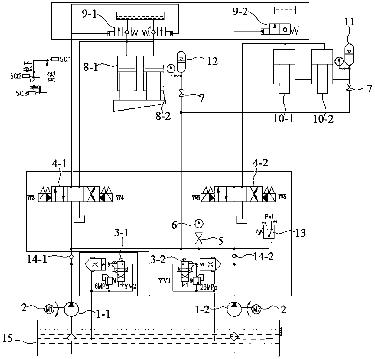
[0045] In view of the deficiencies of the existing hydraulic system of the shearing machine, this embodiment optimizes the structure of the hydraulic system, abandons the disadvantages of the traditional hydraulic system of the shearing machine, and realizes the independent action of the pressing cylinder. Utilizing the cooperation of the high and low pressure oil pump motor unit, and controlling the hydraulic valve through electrical appliances, on the one hand, the simultaneous or sequential return of the shearing cylinder and the pressing cylinder can be realized, which increases the action performance of the machine tool and greatly improves the work efficiency; on the other hand The combined oil supply of double pumps is used to supply oil to the shearing cylinder for rapid downward movement, and then through YV2 power failure, the single-pump oil supply is used for slow-speed high-pressure downward shearing, that is, through the reasonable switching of two sets of high and...


PUM


Abstract

The invention discloses a plate shearing hydraulic control process of plate shears, and belongs to the technical field of forging machines. According to a hydraulic system of the plate shears, an oiloutlet of a first oil pump and an oil outlet of a second oil pump are connected with an opening P of a first electro-hydraulic directional valve, an opening P of a second electro-hydraulic directionalvalve, lower cavities of shearing cylinders, lower cavities of material pressing cylinders, a first energy accumulator and a second energy accumulator through pipelines. An opening A of the first electro-hydraulic directional valve is connected with upper cavities of the shearing cylinders through a first hydraulic control one-way valve, and an opening B of the first electro-hydraulic directionalvalve is directly connected with the upper cavities of the shearing cylinders through a pipeline. An opening A of the second electro-hydraulic directional valve is connected with upper cavities of the material pressing cylinders through a second hydraulic control one-way valve, and an opening B of the second electro-hydraulic directional valve is directly connected with the upper cavities of thematerial pressing cylinders through a pipeline. The hydraulic system of the plate shears is subjected to optimization design, and therefore the machining efficiency of the plate shears can be effectively improved, vibration of a machine can be effectively relieved, blades can be protected, and the service life of the blades can be prolonged easily.

Description

technical field [0001] The invention belongs to the technical field of hydraulic systems, and more specifically relates to a hydraulic control shearing process of a shearing machine. Background technique [0002] Shearing machine (English name: plate shears; guillotine shear) is a kind of forging machinery, which is a machine that uses one blade to make a reciprocating linear motion relative to the other blade to shear the plate. With the help of the moving upper blade and the fixed lower blade, the shearing machine applies a shearing force to the metal sheets of various thicknesses with a reasonable blade gap, so that the sheets are broken and separated according to the required size. At present, the shearing machine products are widely used in aviation, light industry, metallurgy, chemical industry, construction, shipbuilding, automobile, electric power, electrical appliances, decoration and other industries, providing the required special machinery and complete sets of eq...

Claims


Application Information

Patent Timeline
Patent Type & Authority Patents(China)
IPC IPC(8): B23D15/14
CPCB23D15/14
Inventor 石贤锋石贤林郑盼盼王露陶树仁
Owner ANHUI DONGHAI MACHINE MFG CO LTD
Learn More