
Quick-cutting tool positioning structure

A tool positioning and positioning mechanism technology, applied in auxiliary devices, metal processing, manufacturing tools, etc., can solve the problems of waste of space and equipment resources, inability to share positioning trolleys, waste of resources, etc., achieve high switching efficiency and save manual switching time , The effect of convenient model switching

Pending Publication Date: 2018-12-18
SAIC-GM-WULING AUTOMOBILE CO LTD
View PDF7 Cites 0 Cited by
  • Summary
  • Abstract
  • Description
  • Claims
  • Application Information

AI Technical Summary

Problems solved by technology

[0002] The tooling of the panoramic sunroof brazing workstation is a special tooling that can only be used for the production of a single model
This kind of special line structure, the tooling and the base are integrated. If you want to produce other models, you need to dismantle the tooling and rebuild it, or find a new site to build a new workstation, which causes a great waste of site and equipment resources.
[0003] Flexible tooling, tooling switching method is to use a special trolley to push the tripod to the station, and then push the trolley away after switching. It needs to find an additional place to store the trolley, and for models with large changes in length and width, shared positioning cannot be used. car, resulting in waste of resources, positioning the car such as figure 1
In addition, the docking of the trolley and the tooling base requires a ground guiding mechanism, and the structure is more complicated

Method used


Image

  • Quick-cutting tool positioning structure
  • Quick-cutting tool positioning structure
  • Quick-cutting tool positioning structure

Examples


Embodiment Construction

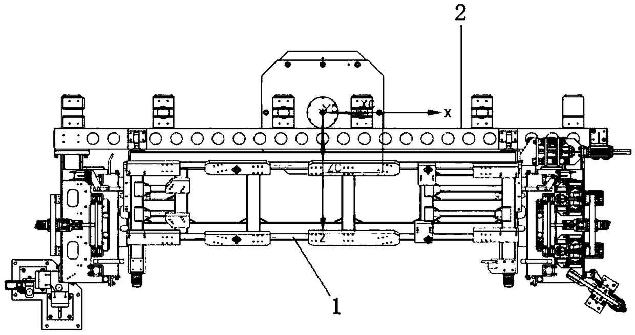
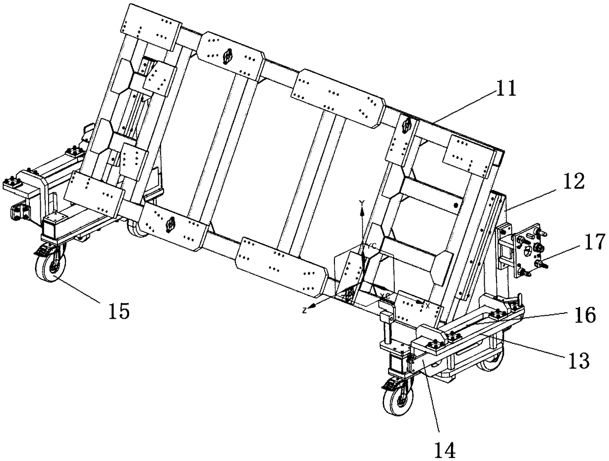
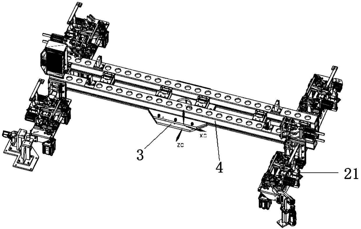
[0018] Such as Figure 1 to Figure 4 As shown, the present invention discloses a quick-cut tool positioning structure, including a ground fixing mechanism 2 and a switchable tool 1. The switchable tool 1 includes a clamp frame 11 and tripods 12 arranged at both ends of the clamp frame 11. The tripod 12 is a right-angled triangular support. The tripod 12 includes a crossbeam, a longitudinal beam and an oblique beam. The longitudinal beam and the crossbeam are arranged perpendicularly. On the inclined beam of a tripod 12, the lower end of the beam of the tripod 12 is provided with a universal wheel 15, and the opposite side of the tripod 12 and the clamp frame 11 is provided with a pressing plate 13 and is located on the pressing plate. The guide plate 14 at the lower end of 13, the tripod 12 is provided with a limit block on the longitudinal outer side, and the pressing plate 13 is provided with two Y-direction lifting pin holes and Y-direction bar-shaped positioning pin holes ...


PUM


Abstract

The invention provides a quick-cutting tool positioning structure. The quick-cutting tool positioning structure comprises a ground fixing mechanism and a switchable tool. The switchable tool comprisesa clamp frame and tripods arranged at two ends of the clamp frame. Universal wheels are arranged at the lower ends of the tripods. Pressing plates and guide plates arranged at the lower ends of the pressing plates are arranged on the outer sides of the tripods. A limiting block is arranged at one end of each tripod. The pressing plates are provided with lifting pin holes and positioning pin holes. The ground fixing mechanism comprises a rotary mechanism and a rotary frame arranged at the upper end of the rotary mechanism, the rotary frame is symmetrically provided with an A face positioning mechanism and a B face positioning mechanism of the same structure. The A face positioning mechanism comprises positioning locking devices corresponding to the tripods at the two ends of the clamp frame respectively. Each positioning locking device comprises a supporting plate, and each supporting plate is provided with a lifting positioning pin matched with the corresponding lifting pin hole, a sliding positioning pin matched with the corresponding positioning pin hole, a clamp head capable of being pressed on the corresponding sliding positioning pin and a guide wheel matched with the corresponding guide plate. The rotary frame is further provided with in-place top blocks matched with the limiting blocks.

Description

technical field [0001] The invention relates to the field of vehicle body manufacturing, in particular to a quick-cut tool positioning device. Background technique [0002] The tooling of the panoramic sunroof brazing workstation is a special tooling, which can only be used for the production of a single model. This kind of special line structure, the tooling and the base are integrated. If the production of other models is to be carried out, the tooling needs to be dismantled and rebuilt, or a new site must be found to build a new workstation, which has caused a great waste of site and equipment resources. [0003] Flexible tooling, tooling switching method is to use a special trolley to push the tripod to the station, and then push the trolley away after switching. It needs to find an additional place to store the trolley, and for models with large changes in length and width, shared positioning cannot be used. car, resulting in waste of resources, positioning the car suc...

Claims


Application Information

Patent Timeline
Patent Type & Authority Applications(China)
IPC IPC(8): B23K3/08B23K3/00
CPCB23K3/00B23K3/08B23K3/087
Inventor 何柳黄丹冯国强
Owner SAIC-GM-WULING AUTOMOBILE CO LTD
Learn More