
Punching device

A technology of punching device and mounting plate, applied in metal processing and other directions, can solve the problems of low production efficiency, low degree of automation, increase labor intensity of operators, etc., and achieve good effect, accurate punching position, and improve the level of production automation. Effect

Pending Publication Date: 2018-12-18
FOSHAN DRAGON TECH
View PDF13 Cites 3 Cited by
  • Summary
  • Abstract
  • Description
  • Claims
  • Application Information

AI Technical Summary

Problems solved by technology

During the processing of the silicone draining basket, the draining hole should be processed on the side wall of the basket body, but the current punching device requires the operator to swing the handle many times to press down the drill bit and turn the basket several times to change the processing position, thus completing the silicone draining. The processing of the entire outer wall circumference of the basket has low production efficiency and low degree of automation, which increases the labor intensity of the operators.

Method used


Image

  • Punching device
  • Punching device
  • Punching device

Examples


Embodiment Construction

[0024] The present invention provides a punching device. In order to make the purpose, technical solution and effect of the present invention clearer and clearer, the present invention will be further described in detail below with reference to the accompanying drawings and examples. It should be understood that the specific embodiments described here are only used to explain the present invention, and are not intended to limit the protection scope of the present invention.

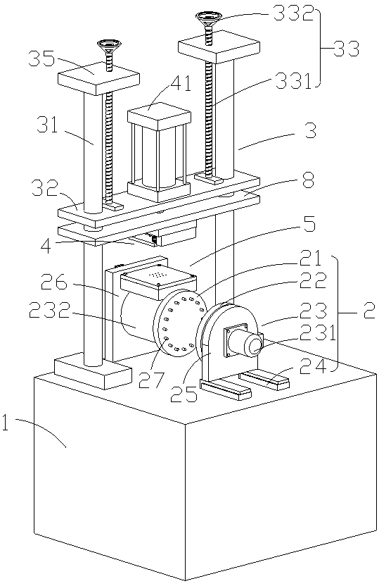
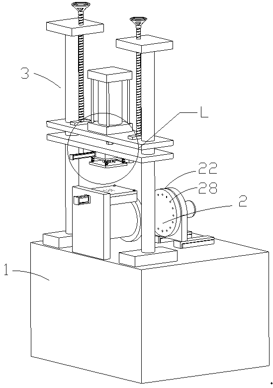
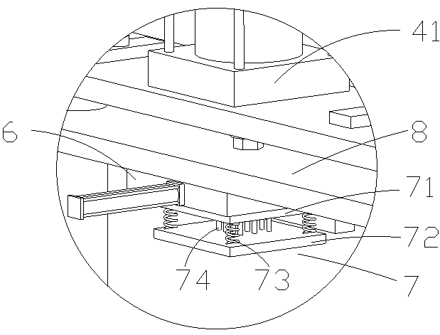
[0025] see Figure 1-Figure 6 , the present invention provides a punching device, comprising a workbench 1, an automatic rotating jig 2 arranged on the workbench, a vertical guide mechanism 3 symmetrically arranged on the left and right sides of the automatic rotating jig, and two vertical guides connected to each other. The punching mechanism 4 of mechanism; Described punching mechanism 4 comprises punching drive assembly 41, is located at the punching pressure platform 5 of automatic rotation fixture up...


PUM


Abstract

The invention discloses a punching device. The punching device comprises a worktable, an automatic rotating clamp arranged on the worktable, vertical guide mechanisms symmetrically arranged on the left side and the right side of the automatic rotating clamp and a punching mechanism connected with the two vertical guide mechanisms. The punching mechanism comprises a punching drive assembly, a punching pressurizing platform arranged on the upper side of the automatic rotating clamp, a waste collecting mechanism and a punching mold arranged at the bottom of the waste collecting mechanism, the output end of the punching drive assembly is connected with the waste collecting mechanism through a guide plate, and the guide plate is in sliding connection with the two vertical guide mechanisms. According to the punching device, after the automatic rotating clamp clamps the bottom of a basket, the punching drive assembly drives the guide plate to drive the punching mold to move in the guide direction of the vertical guide mechanisms to achieve stamping and punching of a silica gel drain basket on the punching pressurizing platform, stamping punching efficiency is high, the effect is good, andthe production automation level is improved.

Description

technical field [0001] The invention relates to the field of processing silica gel drain baskets, in particular to a punching device. Background technique [0002] The drain basket is a mesh basket placed in the sink for water filtration. The general material is mostly stainless steel and plastic. With the development of the main material industry of the home, food-grade silica gel is used as the main material of the drain basket, which is environmentally friendly and non-toxic. It is safe, waterproof, wear-resistant, easy to clean, non-slip, tough and feels good, soft and elastic, and has high tear resistance. It is more durable and non-deformable than similar materials. During the processing of the silicone draining basket, the draining hole should be processed on the side wall of the basket body, but the current punching device requires the operator to swing the handle many times to press down the drill bit and turn the basket several times to change the processing positi...

Claims


Application Information

Patent Timeline
Patent Type & Authority Applications(China)
IPC IPC(8): B26F1/02B26D7/02B26D7/00
CPCB26D7/00B26D7/02B26F1/02B26D2007/0018
Inventor 熊道武魏新安
Owner FOSHAN DRAGON TECH
Learn More