[0029] In order to facilitate the understanding of the present invention, the following description will be given in conjunction with the drawings and embodiments.
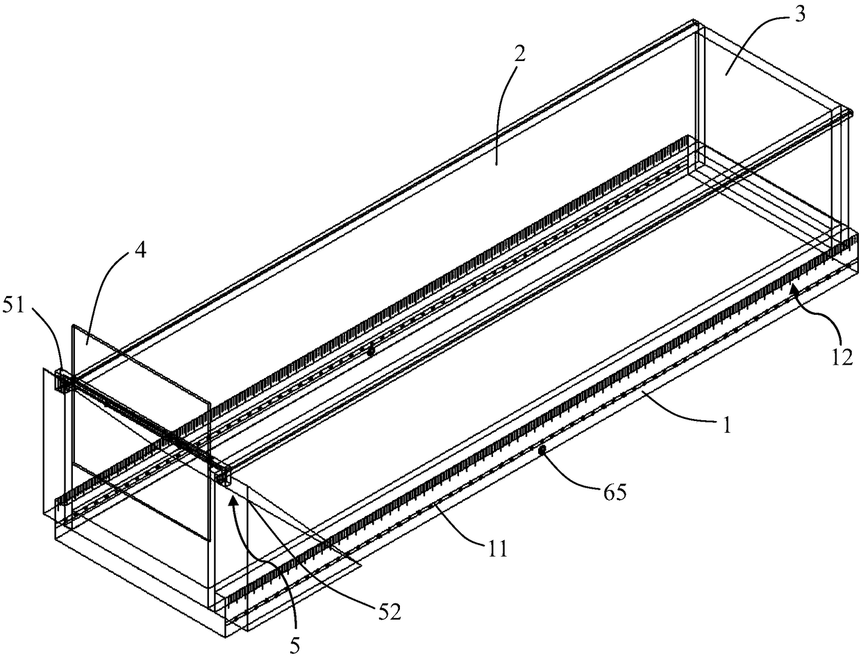
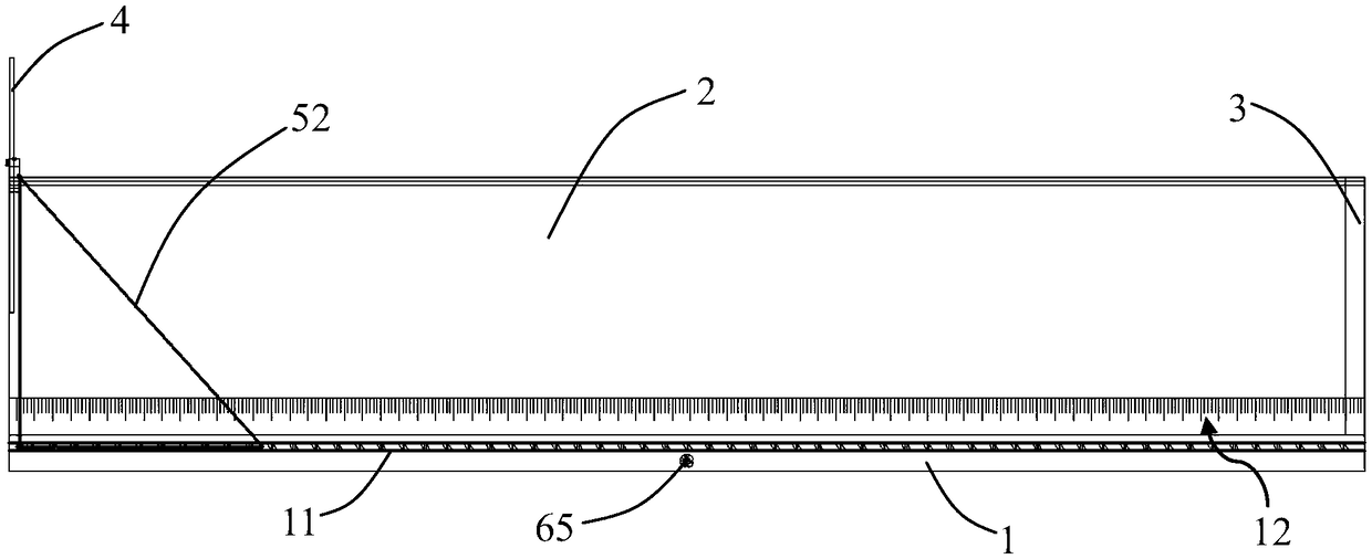
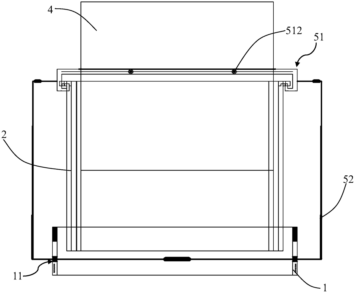
[0030] See Figure 1 to Figure 5 with Figure 7 It can be seen that the present invention discloses a detachable concrete lintel mold, including: bottom mold 1, side mold 2, first baffle 3, second baffle 4 and movable frame 5; specifically, the bottom mold 1 A first chute 11 is provided on opposite sides respectively. The two side molds 2 are relatively detachably mounted on the bottom mold 1 and correspond to the two first chutes 11 one by one. The bottom mold 1 and the two side plates 2 are surrounded to form two ends And the concrete pouring space with the top opening, the two sides of the first baffle 3 are detachably connected to the two side molds 2 and are used to seal the first end opening of the concrete pouring space, and the two sides of the second baffle 4 are attached to the two sides The inner wall of the side form 2 is used to seal the second end opening of the concrete pouring space, and the second baffle 4 is slidably installed in the two first chutes 11 through a movable frame 5. In this embodiment, the movable frame 5 is used to drive the second baffle 4 to slide along the first chute 11 to realize the adjustment of the length of the concrete lintel mold; in this embodiment, between the side mold 2 and the bottom film 1 Both the mold 2 and the first baffle 3 can be detached and connected, which is convenient for the installation and disassembly of the concrete lintel mold, and has good turnover. In the present invention, the bottom mold 1, the side mold 2, the first baffle 3 and the second baffle 4 are all selected steel plate structures, which can ensure the surface quality of the concrete lintel after pouring and forming.
[0031] Further, the movable frame 5 includes a sliding rod 521 slidably arranged in the first sliding groove 11 and a sliding beam 51 detachably connected to the sliding rod 521. The sliding beam 51 is slidably arranged on the top of the side mold 2 to slide The moving beam 51 is provided with a through groove 511, and the second baffle 4 is inserted into the through groove 511. In this embodiment, the sliding rod 521 is used to slide along the first chute 11 to adjust the distance between the first baffle 3 and the second baffle 4 inserted in the through groove 511, so as to realize the passage of concrete Adjustment of beam mould length.
[0032] Such as figure 1 , image 3 , Picture 9 with Picture 10 As shown, it also includes a locking device, which is arranged between the bottom mold 1 and the movable frame 5. The locking device includes a pressing plate 61 placed in the first chute 11 and a gear assembly for driving the pressing plate 61 to move up and down , The pressing plate 61 is located below the sliding rod 521 and is formed with a clamping tooth 62 for clamping the movable sliding rod 521. In this embodiment, a locking device is used to lock the movable frame 5 after sliding into position on the bottom mold 1 to prevent the movable frame 5 from slipping during the pouring process and ensure that the length of the poured concrete lintel meets the actual length requirement.
[0033] Further, the gear assembly includes a first gear 63, a second gear 64, and a chain 66 or a belt 66 connected to the first gear 63 and the second gear 64 at intervals along the height direction of the bottom mold 1. The pressure plate 61 passes through a fixed rod 66 Fixed to the chain 66 or belt 66. In actual use, by rotating the first gear 63 or the second gear 64, the chain 66 or the belt 66 is driven to move up and down, and then the fixing rod 66 fixed to the chain 66 or the belt 66 drives the pressure plate 61 to move up and down; Picture 9 with Picture 10 As shown, before sliding the movable frame 5 (sliding rod 521) along the first chute 11, by rotating the first gear 63 wheel or the second gear 64, the pressing plate 61 is driven to move downward to complete the unlocking of the sliding rod 521 , And then move the sliding rod 521 to the corresponding position along the setting direction of the first sliding groove 11, and then rotate the first gear 63 or the second gear 64 in the opposite direction to drive the pressure plate 1 to move upwards, and the clamping teeth 62 on the pressure plate 61 are used to clamp The sliding rod 521 completes the locking of the movable frame 5 on the bottom mold 1. Furthermore, it also includes a rotating handle 65 coaxially connected to the first gear 63 or the second gear 64 to facilitate driving the first gear 63 or the second gear 64 to rotate.
[0034] Such as figure 1 , image 3 , Image 6 with Figure 7 As shown, the top of the side mold 2 is formed with a second sliding groove 21, and the end of the sliding beam 51 is formed with a protrusion 514 slidably disposed in the second sliding groove 21. The functions of the sliding beam 51 are: 1. Realize the vertical positioning of the second baffle 4; 2. Connect the two side molds 2, improve the structural strength of the concrete lintel mold, and ensure the overall stability of the concrete lintel mold.
[0035] Furthermore, the sliding beam 51 is provided with a threaded hole 513 penetrating through the through groove 511, and the threaded hole 513 is screwed with a screw connection 512 for locking the second baffle 4 on the sliding beam 51. The positioning of the second baffle 4 on the sliding beam 51 is achieved by rotating the screw connection 512.
[0036] Such as Figure 8 As shown, the movable frame 5 includes two frame units 52 that are detachably connected and symmetrically arranged. The frame unit 52 includes a sliding rod 521 and a fixing frame 522 fixed to the sliding rod 51. The sliding beam 51 is detachably connected to the fixing frame. 522; Easy to install and disassemble the movable frame 5. In this embodiment, the sliding rod 521 and the fixed frame 522 are connected to form a prismatic frame structure, which ensures the stability of the overall structure of the movable frame. In the present invention, a first connecting rod 523 is connected to the fixing frame 522, a second connecting rod is connected to the sliding beam 51, and the first connecting rod 523 is detachably connected to the second connecting rod; specifically, the first connecting rod The 523 and the second connecting rod are detachably connected together by tightening components (including bolts) or a hoop structure to facilitate the disassembly and assembly of the movable frame.
[0037] Such as Figure 4 As shown, the bottom mold 1 is provided with a first card slot 13 and a second card slot 14, the side mold 2 is clamped in the first card slot 13, and the first baffle plate 3 is clamped in the second card slot 14; The side mold 2 is clamped in the first slot 13 to realize the connection between the side mold 2 and the bottom mold 1, and the first baffle 3 is clamped in the second slot 14 to realize the first baffle 3 and the bottom. Connection between Mode 1. Furthermore, the side mold 2 and the first baffle 3 are spliced and connected; specifically, the splicing part of the side mold 2 is formed with a clamping part, and the splicing part of the second baffle 4 is formed with a clamp for the clamping part. The third card slot facilitates the disassembly and assembly of the concrete lintel mold.
[0038] Further, such as figure 1 with Figure 4 As shown, the side surface of the bottom mold 1 is formed with a scale 12 arranged along the arrangement direction of the first chute 11, and the zero scale line of the scale 12 is located at the position of the first baffle 3; it is convenient to accurately control the length of the concrete lintel.
[0039] In actual use, the steps for adjusting the length of the concrete lintel mold are as follows: first insert the second baffle 4 into the through groove 511, and lock it on the sliding beam 51 by the screw connection 512, and then move along the first sliding groove 11 Slide the movable frame 5 to the position of the corresponding scale, and then loosen the screw connection 512. The second baffle 4 falls freely onto the bottom mold 1 under its own gravity, and then rotates the screw connection 512 in the opposite direction. The second baffle 4 is locked on the sliding beam 51 to realize the sliding and positioning of the second baffle 4, and then complete, the length of the concrete lintel mold is adjusted.
[0040] The beneficial effects of the removable concrete lintel mold of the present invention include:
[0041] 1. Drive the movable frame to slide along the first chute to drive the second baffle to slide relative to the first chute, thereby changing the distance between the first baffle and the second baffle to realize the concrete lintel mold length Compared with the inability to adjust the length of the concrete lintel mold in the prior art, it has better adaptability; the bottom form, the side form, the first baffle and the second baffle are enclosed to form a concrete lintel The accommodating space is convenient for pouring the concrete of the concrete lintel.
[0042] 2. By opening a through slot on the sliding beam, when the movable frame slides into place, insert the second baffle into the through slot, the second baffle will fall freely onto the bottom mold under its own gravity, and then By rotating the screw connection, the second baffle is locked on the sliding beam, which facilitates the sliding and positioning of the second baffle.
[0043] 3. The detachable connection between the two frame units, the detachable connection between the frame unit and the sliding beam, the side mold is clamped in the first slot, the first baffle is clamped in the second slot, and the side mold It is connected to the first baffle through assembly, which is convenient for the installation and disassembly of the concrete lintel mold, and has good turnover.
[0044] 4. The bottom mold, side mold, second baffle and first baffle select steel plates instead of traditional wooden molds, which can ensure the surface quality of the concrete lintel; the concrete lintel mold of the present invention can avoid nailing in the prior art Making wood molds wastes manpower, material resources and construction materials.
[0045] 5. Use the locking device to lock the movable frame after sliding in place on the bottom form, and lock the second baffle on the sliding beam to realize the positioning of the second baffle and avoid the concrete lintel pouring process In the middle, the second baffle slips, ensuring that the pouring length of the concrete lintel meets the actual construction requirements.
[0046] The above are only preferred embodiments of the present invention, and do not limit the present invention in any form. Although the present invention has been disclosed as above in preferred embodiments, it is not intended to limit the present invention. Anyone skilled in the art, Without departing from the scope of the technical solution of the present invention, when the technical content disclosed above can be used to make slight changes or modification into equivalent embodiments with equivalent changes, but any content that does not depart from the technical solution of the present invention, according to the technology of the present invention Essentially, any simple modifications, equivalent changes and modifications made to the above embodiments still fall within the scope of the technical solutions of the present invention.
[0047] It should be noted that the structure, ratio, size, etc. shown in the accompanying drawings in this specification are only used to match the content disclosed in the specification for the understanding and reading of those familiar with this technology, and are not intended to limit the present invention. The limited conditions that can be implemented do not have any technical significance. Any structural modification, proportional relationship change or size adjustment should still be implemented without affecting the effects and objectives that can be achieved by the present invention. It is within the scope of the technical content disclosed in the present invention.