
Demolding mechanism and method

A technology of demolding mechanism and demoulding device, applied in ceramic molding machines, auxiliary molding equipment, unloading devices, etc., can solve the problems of brick wear, incomplete demoulding, sticking, etc., to avoid wear and ensure integrity , Improve the effect of separation quality

Pending Publication Date: 2018-12-18
大连范特西西科技有限公司
View PDF11 Cites 4 Cited by
  • Summary
  • Abstract
  • Description
  • Claims
  • Application Information

AI Technical Summary

Problems solved by technology

[0003] The demoulding of the existing bricks is easy to cause wear to the bricks during the moving process, and at the same time, sticking results in incomplete demoulding

Method used


Image

  • Demolding mechanism and method
  • Demolding mechanism and method
  • Demolding mechanism and method

Examples


Embodiment 1

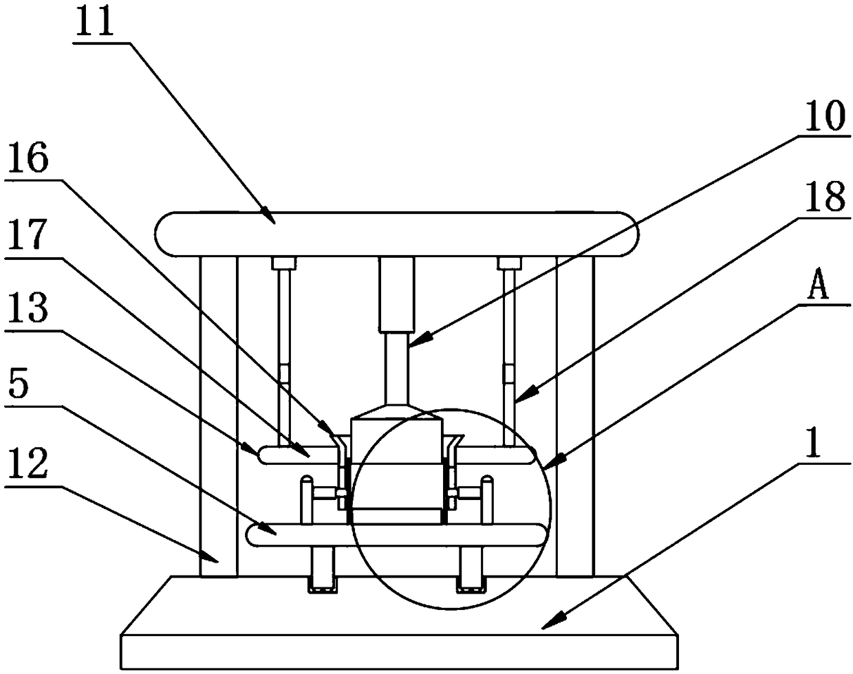
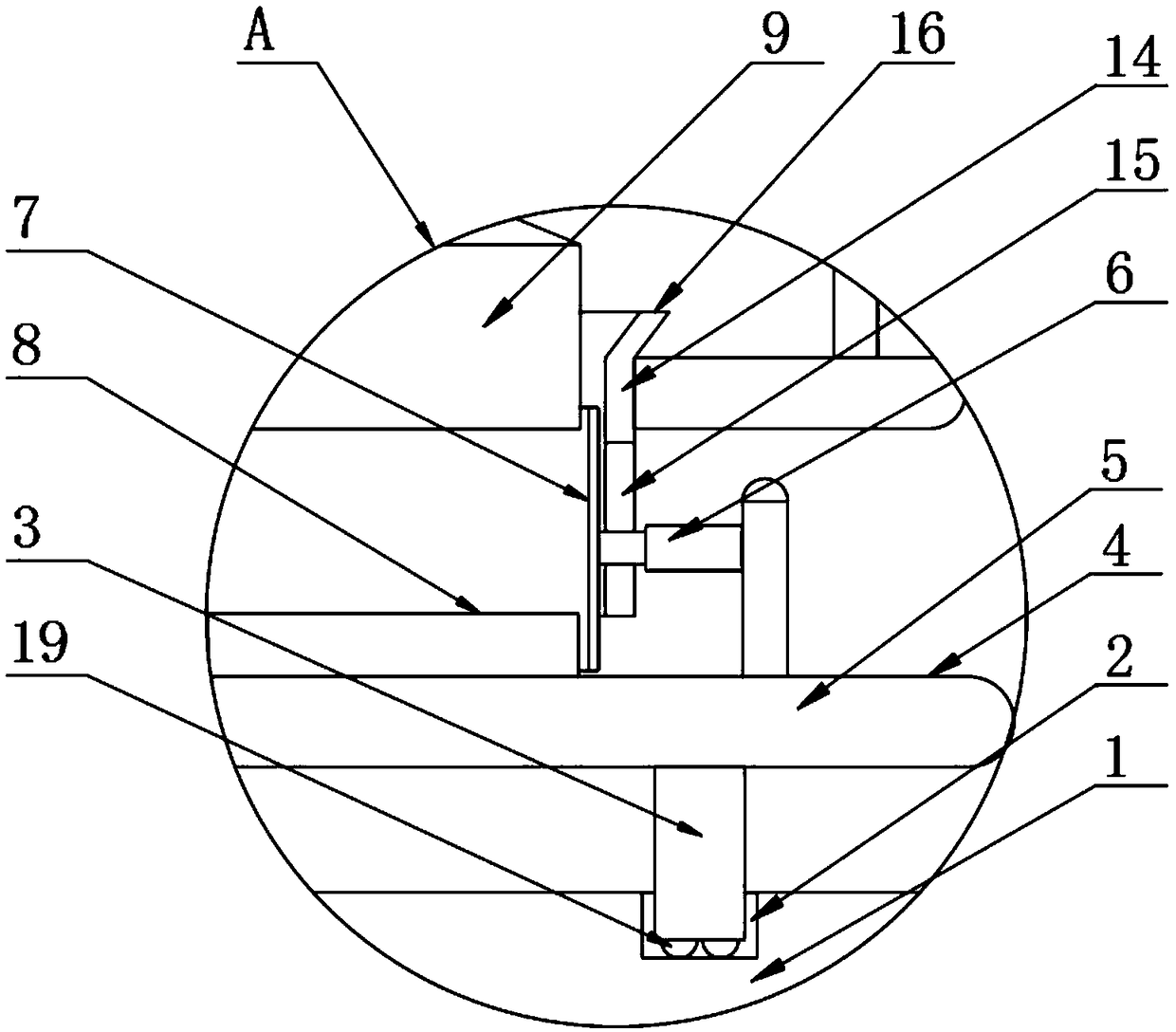
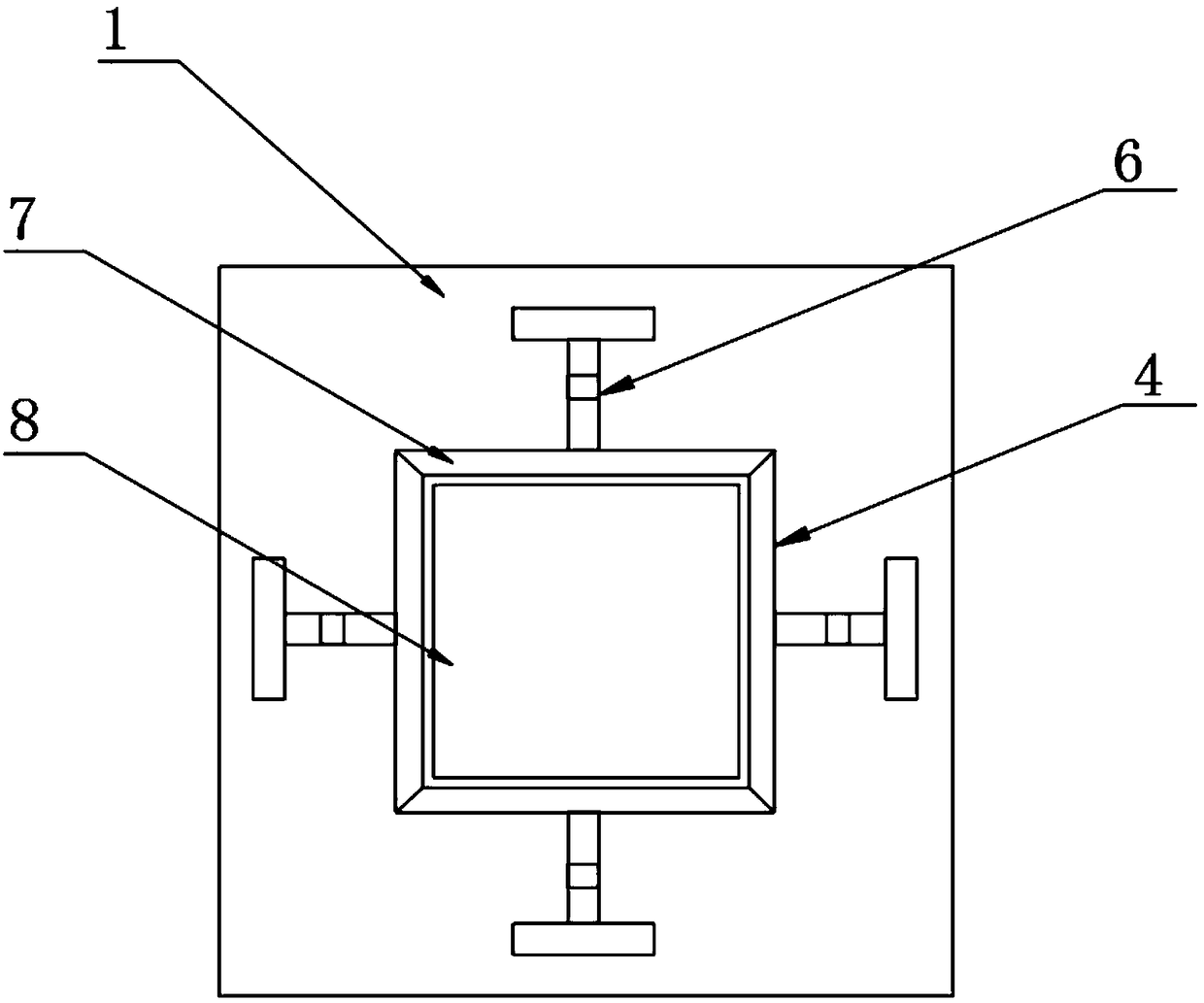
[0024] The present invention provides such as Figure 1-3 A demoulding mechanism shown includes a base 1, the surface of the base 1 is provided with a chute 2, the inside of the chute 2 is provided with a slider 3, and the slider 3 is slidably connected with the chute 2, the The top of the slider 3 is provided with a demoulding device 4, including a fixed plate 5, the top of the fixed plate 5 is provided with a vertical plate, one side of the vertical plate is provided with a first hydraulic rod 6, and one side of the first hydraulic rod 6 is A shaping plate 7 is provided, and a pressure table 8 is arranged on one side of the shaping plate 7, and the output shaft of the first hydraulic rod 6 is fixedly connected with the shaping plate 7, and a pressure block 9 is arranged on the top of the shaping plate 7, and the pressure block 9 is arranged on the top of the shaping plate 7. The top of the block 9 is provided with a second hydraulic rod 10, the output shaft of the second hyd...

Embodiment 2

[0034] A demoulding method, comprising said demoulding mechanism, also includes the following steps:

[0035] S1: The brick material enters into the mold cavity surrounded by four shaping plates 7;

[0036] S2: Open the second hydraulic rod 10 and the electric telescopic rod 18, the second hydraulic rod 10 pushes the briquetting block 9 to squeeze the brick material, and at the same time, the electric telescopic rod 18 drives the material guide cylinder 14 to rise;

[0037] S3: Then open the first hydraulic rod 6, the first hydraulic rod 6 drives the four shaping plates 7 to separate horizontally from the brick embryo, and the pressing table 8 makes the brick embryo at a higher position, which is used to move the brick embryo, and at the same time passes through the slider 3. The fixed plate 5 is moved, and the brick embryo is completely separated and demoulded.


PUM


Abstract

The present invention discloses a demolding mechanism and method. The demolding mechanism comprises a base, wherein the surface of the base is provided with a sliding slot, a sliding block is arrangedinside the sliding slot, the sliding block is slidably connected with the sliding slot, and the top of the sliding block is provided with a demolding device; the top of the demolding device is provided with a fixing plate, one side of the fixing plate is provided with first hydraulic rods, one sides of the first hydraulic rods are provided with shaping plates, and one sides of the shaping platesare provided with a pressing platform; output shafts of the first hydraulic rods are fixedly connected with the shaping plates, the tops of the shaping plates are provided with a pressing block, the top of the pressing block is provided with a second hydraulic rod, and an output shaft of the second hydraulic rod is fixedly connected to the pressing block; and a top plate is arranged on the top ofthe second hydraulic rod. The invention adopts the demolding device, and a brick material enters into a mold cavity formed by the four shaping plates, and the first hydraulic rods drive the four shaping plates to be horizontally separated from a green brick, which is beneficial to effectively avoiding the wear of the green brick during demolding the green brick.

Description

technical field [0001] The invention relates to the technical field of manufacturing energy-saving building materials and green building materials, in particular to a demoulding mechanism and method. Background technique [0002] The demoulding mechanism of the prior art brick press generally includes an upper beam, a formwork beam, a base, a guide column, a mold and a demoulding oil cylinder, and the guide column is fixedly connected with the base and the upper beam to form a closed frame. Between the base and the upper beam, slide on the guide column. The mold includes an upper punch, a lower punch and a mold frame. The lower punch is fixedly connected to the base, and the mold frame is fixedly connected to the mold frame beam. The cylinder end of the demoulding cylinder It is hinged or fixedly connected to the upper beam, and the piston rod end is fixedly connected to the formwork beam. In this way, when the brick press presses the adobe, the demoulding cylinder moves the...

Claims


Application Information

Patent Timeline
Patent Type & Authority Applications(China)
IPC IPC(8): B28B13/06B28B17/00
CPCB28B13/065B28B17/00
Inventor 张梅
Owner 大连范特西西科技有限公司
Learn More