Fault detection device and method of elevator braking control device

A control device and elevator braking technology, applied in the field of elevator accessories, can solve problems such as emergency stop of elevator car, failure of braking system, etc.

Active Publication Date: 2018-12-18
SHANGHAI MITSUBISHI ELEVATOR CO LTD
View PDF6 Cites 1 Cited by
  • Summary
  • Abstract
  • Description
  • Claims
  • Application Information

AI Technical Summary

Problems solved by technology

[0003] The disadvantage of this braking system is that once the wire rope between the speed governor and the tensioner is broken or other failures occur, the braking s

Method used


Image

  • Fault detection device and method of elevator braking control device
  • Fault detection device and method of elevator braking control device
  • Fault detection device and method of elevator braking control device

Examples


Embodiment Construction

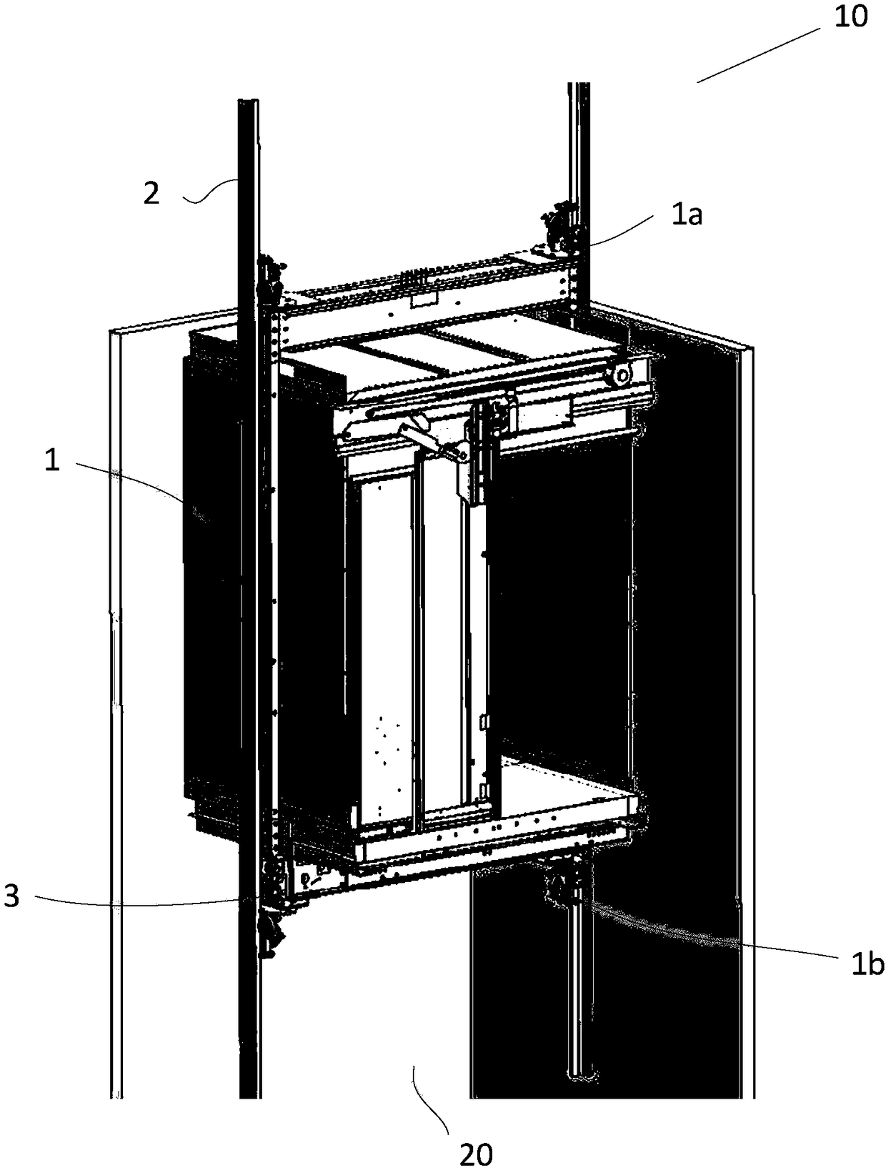
[0064] Such as figure 1 As shown, the present invention has the elevator 10 of the fault detection device of the elevator braking control device, including a car 1, a T-shaped guide rail 2 is fixedly arranged in the running channel 20 of the car 1, and the car 1 is movably arranged on the T-shaped guide rail 2 Inside, the car 1 can run up and down along the T-shaped guide rail 2; the upper and lower parts of the car 1 are respectively provided with guide pieces 1a and 1b.

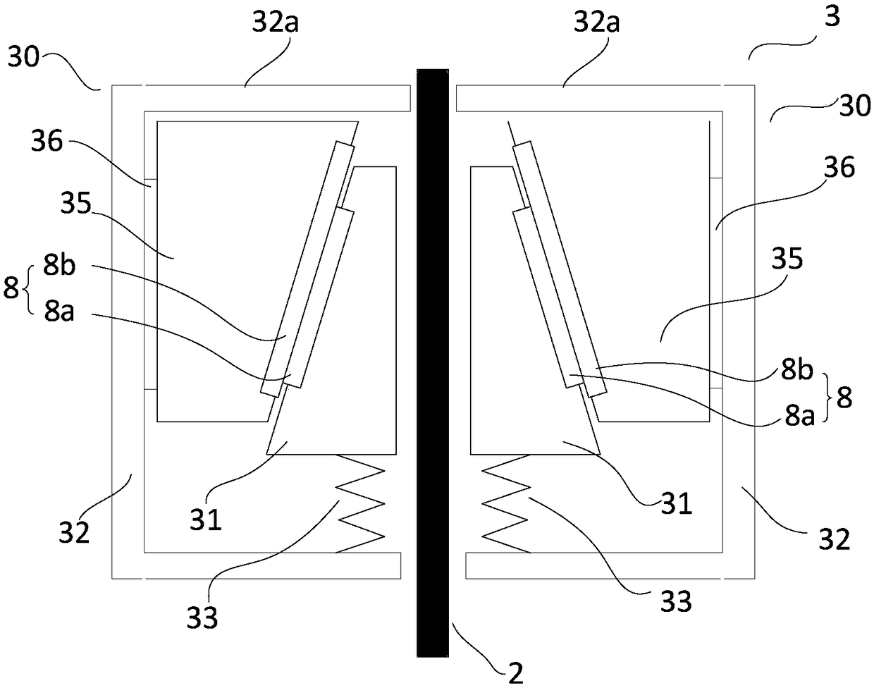
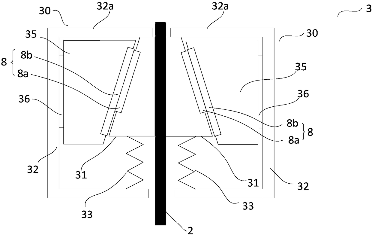
[0065] Such as figure 2 As shown, the fault detection device of the elevator brake control device includes a brake assembly 30, and the brake assembly includes a brake block 31, and the brake block 31 is arranged on one side of the guide rail 2, and the braking surface of the brake block 31 ( That is, an angle is formed between the front near the guide rail 2) and the guide surface (i.e., away from the back of the guide rail 2), so that the brake block 31 is wedge-shaped (that is, the guide surface of the...


PUM


Abstract

The invention discloses a fault detection device of an elevator braking control device. The fault detection device comprises at least two groups of braking components arranged on an elevator lift car,and a control unit for controlling the braking components through an electronic signal according to the information of the elevator lift car. The fault detection device of the elevator braking control device detects the fault of the elevator braking control device through the control unit by depending on the status information of an electromagnetic actuator. When the elevator braking control device breaks down, the fault detection device can ensure that the braking is still effective, and brakes an elevator after the elevator runs to the leveling of a landing, thereby preventing passengers from getting trapped.

Description

technical field [0001] The invention relates to an elevator accessory, in particular to a fault detection device used in an elevator brake control device. The invention also relates to a fault detection method of an elevator braking control device. Background technique [0002] Current elevators generally include a safety system consisting of braking devices, mechanical overspeed governors, tensioning pulleys and wire ropes. The subsystem consisting of speed limiter, tensioner and wire rope includes two functions: one is to detect the running speed of the elevator; the other is to trigger the braking device to brake when the speed exceeds the preset speed. Generally, the overspeed governor is set on the upper part of the hoistway or the machine room floor, the tension pulley is set in the bottom pit, and the wire rope forms a closed loop between the overspeed governor and the tension pulley. When it is detected that the elevator exceeds the preset speed, the speed limiter ...

Claims


Application Information

Patent Timeline
IPC IPC(8): B66B5/18B66B5/00
CPCB66B5/0031B66B5/18
Inventor 徐若育茅顺周俊帆
Owner SHANGHAI MITSUBISHI ELEVATOR CO LTD
Why Eureka
Try Eureka