A sliding support seat for hydraulic hammer rotation and transposition

A support seat and hydraulic hammer technology, which is applied in construction, foundation structure engineering, sheet pile walls, etc., can solve the problems of large manpower labor, complicated and time-consuming process, etc., achieve the effect of simple structure, convenient use, and avoid frequent disassembly of hydraulic hammer

Active Publication Date: 2020-04-07
诸大淼
View PDF3 Cites 2 Cited by
  • Summary
  • Abstract
  • Description
  • Claims
  • Application Information

AI Technical Summary

Problems solved by technology

The hydraulic hammer is heavy. When the pile driver moves for a long distance, in order to reduce the width and weight of the machine body, the hydraulic hammer needs to be dismantled and transported separately, and then the hydraulic hammer is assembled to the machine body when it is used. The process is complicated and time-consuming, and the manual labor is very Big

Method used


Image

  • A sliding support seat for hydraulic hammer rotation and transposition
  • A sliding support seat for hydraulic hammer rotation and transposition
  • A sliding support seat for hydraulic hammer rotation and transposition

Examples


Embodiment Construction

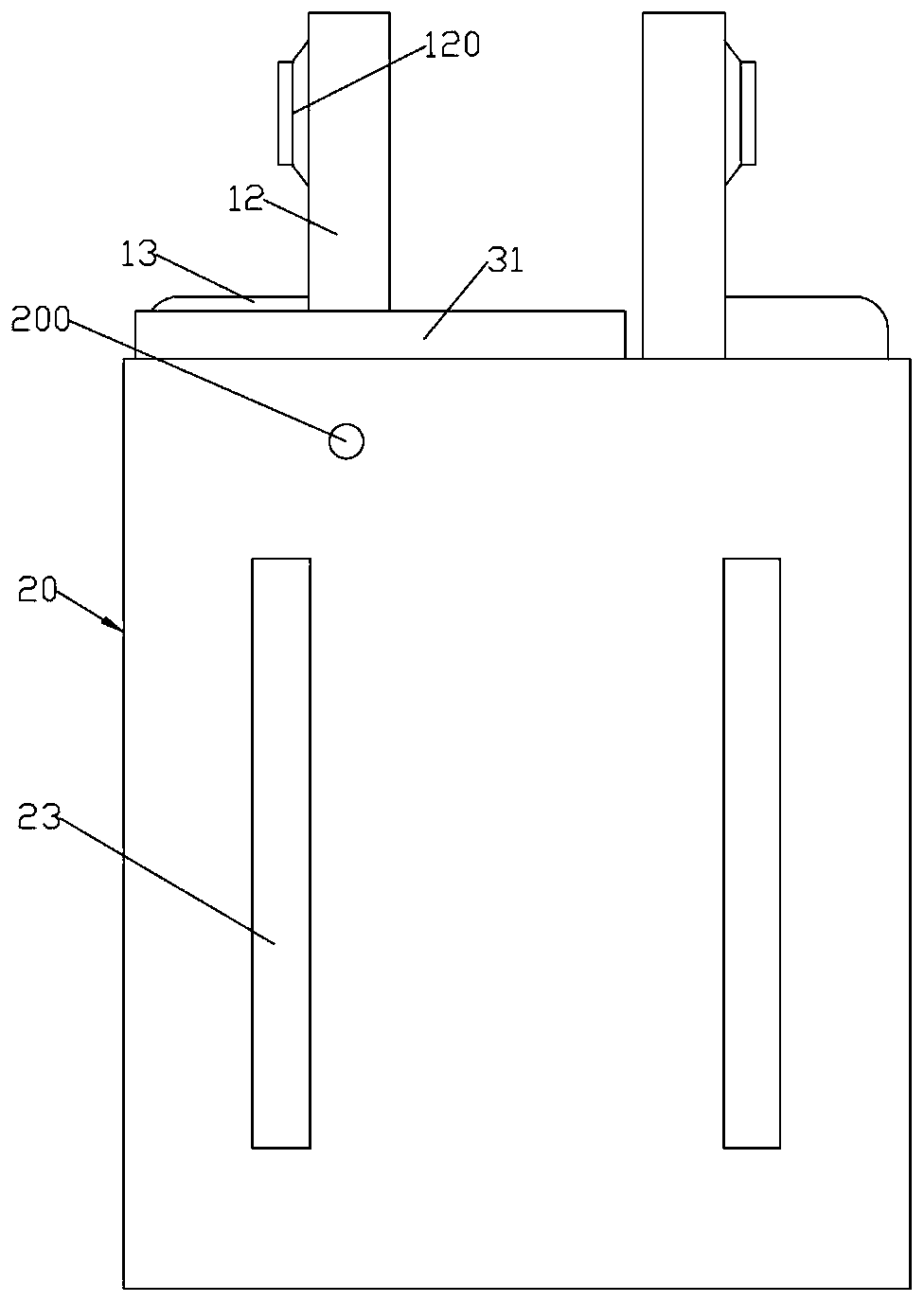
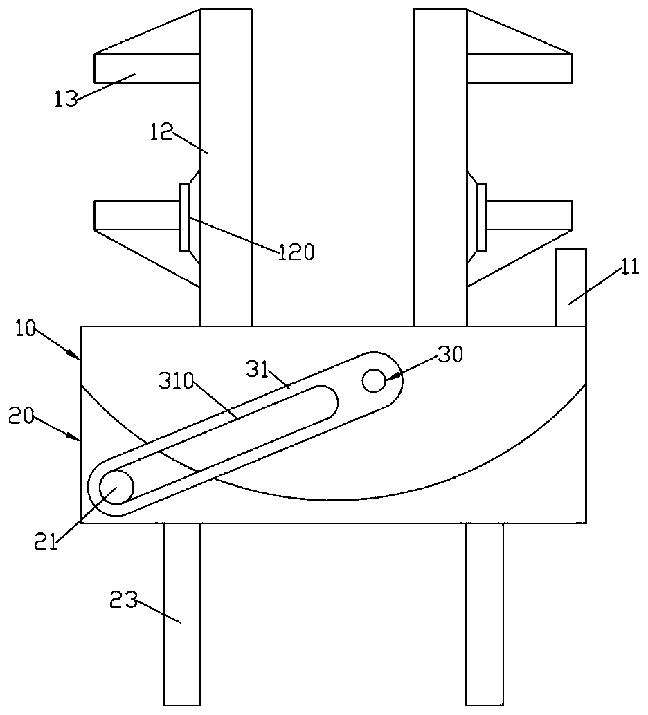
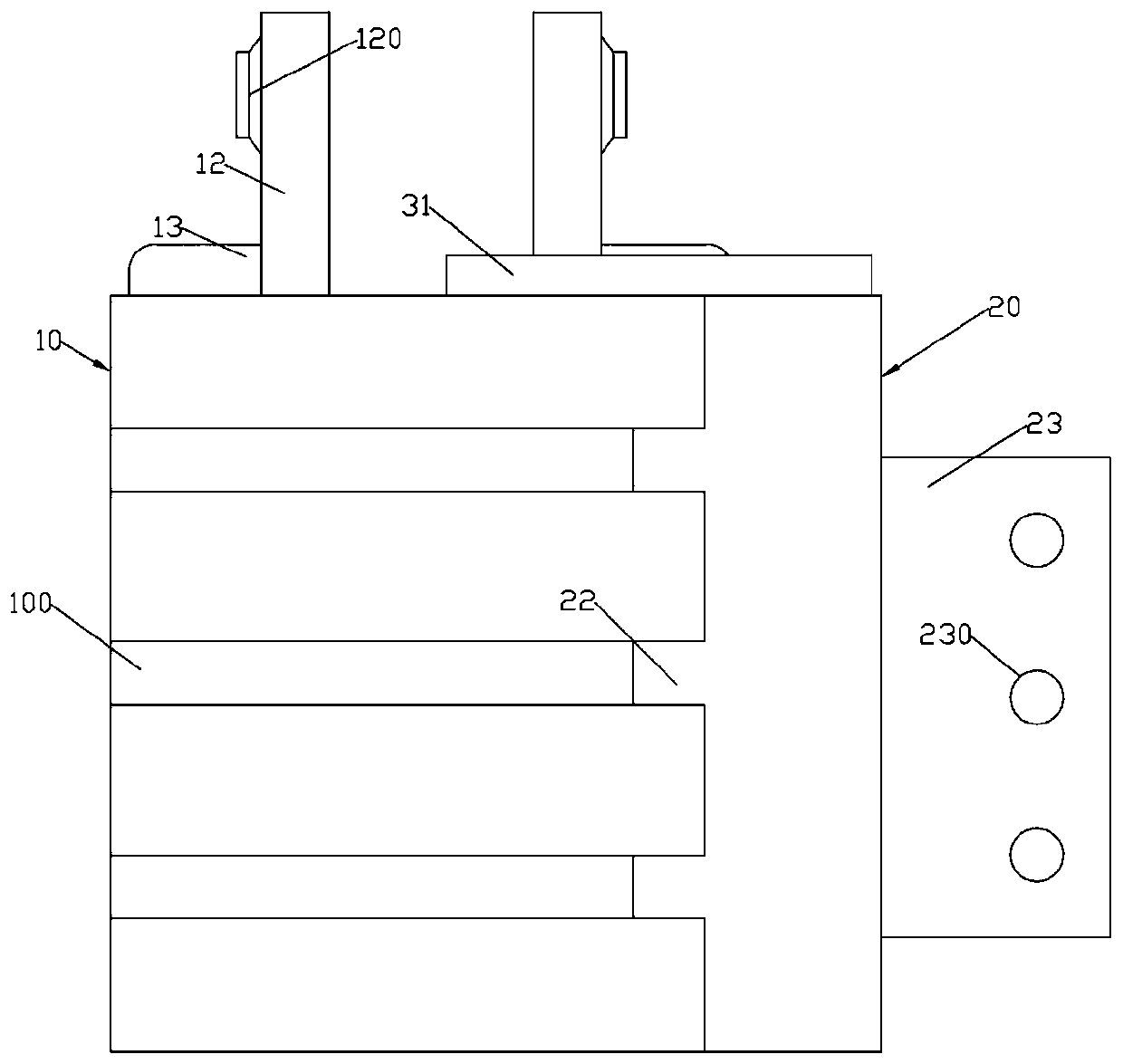
[0015] Such as Figure 1 ~ Figure 4 As shown, a sliding support seat for hydraulic hammer rotary transposition includes a cuboid main support plate 10 whose front end surface is formed as an arc surface and a secondary support plate 20 whose rear end surface is formed as an arc surface; the main support plate 10 A pair of symmetrically arranged slide plates 12 are vertically welded on the rear end face; the rear end face of the auxiliary support plate 20 is coaxially arranged with the front end face of the main support plate 10; Mounting plate 23; the front end surface of the main support plate 10 is formed with some circular arc-shaped sliding grooves 100 distributed up and down; The end surface is formed with a number of sliding guide rails 22 distributed up and down and matched with the sliding groove 100; the upper end surface of the main support plate 10 is fixed with a rotary hydraulic cylinder 30; the output shaft of the rotary hydraulic cylinder 30 is fixed with a driv...


PUM


Abstract

The invention discloses a sliding support seat with a hydraulic hammer capable of rotating to achieve transposition. The sliding support seat comprises a main supporting plate with the front end faceformed in an arc surface cuboid shape and an auxiliary supporting plate with the rear end face formed in an arc surface shape. The rear end face of the auxiliary supporting plate and the front end face of the main supporting plate are arranged with the same axis and the same diameter. A plurality of arc-shaped sliding grooves which are distributed up and down and arranged in a left-right penetrating mode are formed in the front end face of the main supporting plate. The sliding grooves and the rear end face of the main supporting plate are arranged coaxially. A plurality of sliding guide railswhich are distributed up and down and matched with the sliding grooves are formed on the rear end face of the auxiliary supporting plate. A rotating hydraulic cylinder is fixed on the upper end faceof the main supporting plate. A driving plate is fixed to an output shaft of the rotating hydraulic cylinder. A long-hole-shaped drive sliding groove is formed in the driving plate. A cylindrical driving column matched with the drive sliding groove is formed at the left end of the upper end face of the auxiliary supporting plate. The driving column is inserted in the drive sliding groove. The sliding support seat with the hydraulic hammer capable of rotating to achieve transposition saves time and labor, prevents the hydraulic hammer from being disassembled frequently, and is simple in structure and convenient to use.

Description

technical field [0001] The invention relates to the technical field of hydraulic hammers, in particular to a sliding support seat for rotary displacement of hydraulic hammers. Background technique [0002] The pile driver slides up and down in the guide rail through the hydraulic hammer to complete the pile driving work. The hydraulic hammer is heavy. When the pile driver moves for a long distance, in order to reduce the width and weight of the machine body, the hydraulic hammer needs to be dismantled and transported separately, and then the hydraulic hammer is assembled to the machine body when it is used. The process is complicated and time-consuming, and the manual labor is very Big. Contents of the invention [0003] The object of the present invention is to provide a sliding support seat for rotary displacement of hydraulic hammer, which includes a cuboid main support plate whose front end surface is formed into an arc surface The rear end surface of the auxiliary s...

Claims


Application Information

Patent Timeline
Patent Type & Authority Patents(China)
IPC IPC(8): E02D7/16
CPCE02D7/16
Inventor 徐亚维
Owner 诸大淼
Why Eureka
Try Eureka