New material machining device capable of automatically changing tools by utilizing gear circulating movement

An automatic tool changer and processing device technology, which is applied in positioning devices, metal processing equipment, metal processing machinery parts, etc., can solve the problems of increasing the processing cost of new materials, wasting new metal materials, and loose tool clamping, etc., to achieve saving Tool change time, reduce tool change time, and avoid the effect of unreliable installation

Inactive Publication Date: 2020-06-19
姚利娟
View PDF6 Cites 1 Cited by
  • Summary
  • Abstract
  • Description
  • Claims
  • Application Information

AI Technical Summary

Problems solved by technology

[0003] When processing new metal materials, milling machines are usually used for processing. Since different new metal materials have different hardness and toughness, when milling new metal materials, it is necessary to replace milling cutters of different specifications according to different new metal materials. At the same time, when selecting different processing procedures for the same new metal material, it is also necessary to replace different tools. However, the existing processing equipment can only install one tool. Only when new tools can be replaced, the tool change process is cumbersome, time-consuming and labor-intensive, which greatly wastes processing efficiency, and in the process of frequent tool changes, it is easy to cause the tool to be clamped weakly due to work fatigue, resulting in tool collapse , which not only leads to damage of new materials and waste of new metal materials, but also increases tool loss and increases the processing cost of new materials

Method used


Image

  • New material machining device capable of automatically changing tools by utilizing gear circulating movement
  • New material machining device capable of automatically changing tools by utilizing gear circulating movement
  • New material machining device capable of automatically changing tools by utilizing gear circulating movement

Examples


Embodiment Construction

[0026] The following will clearly and completely describe the technical solutions in the embodiments of the present invention with reference to the accompanying drawings in the embodiments of the present invention. Obviously, the described embodiments are only some, not all, embodiments of the present invention. Based on the embodiments of the present invention, all other embodiments obtained by persons of ordinary skill in the art without making creative efforts belong to the protection scope of the present invention.

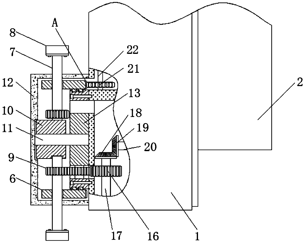
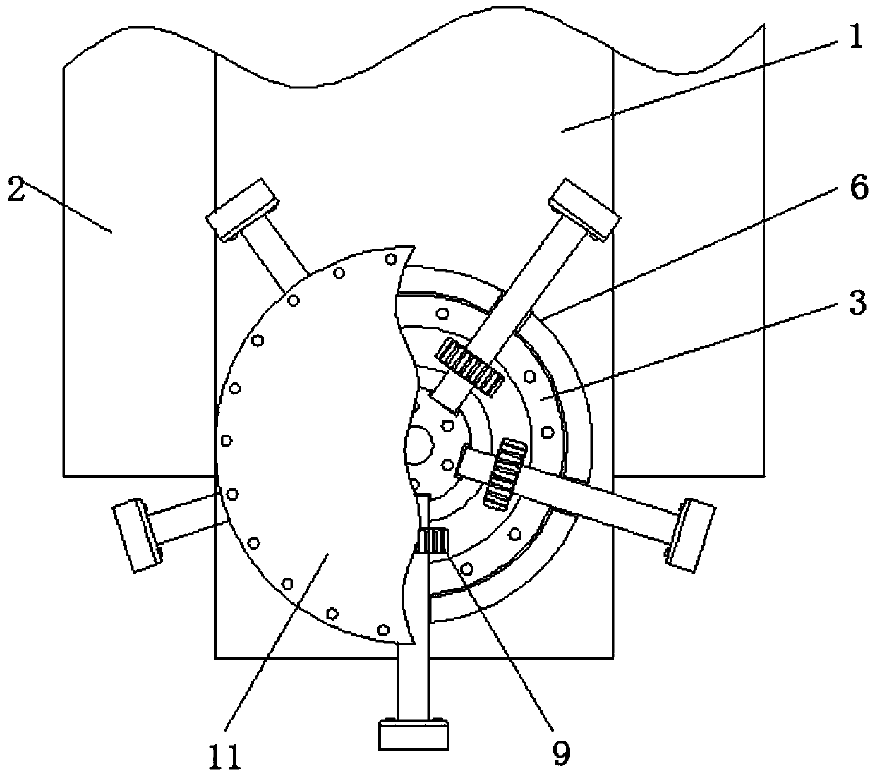
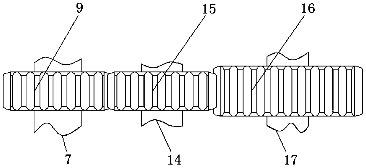
[0027] see Figure 1-4 , a new material processing device that can automatically change tools by using gear turnover motion, including a lifting table 1, a frame 2, an outer slip ring 3, a chute 4, a sliding pin 5, a tool changer 6, a cutting shaft 7, and a tool holder 8. Cutting gear 9, positioning block 10, fixed rod 11, fixed cover 12, fixed ring 13, transition shaft 14, transition gear 15, connecting gear 16, connecting shaft 17, first bevel gear 18, secon...


PUM


Abstract

The invention relates to the technical field of new materials and discloses a new material machining device capable of automatically changing tools by utilizing the gear circulating movement. A lifting table is included, and a rack is connected to the exterior of the lifting table in a sliding manner; an outer slide ring is connected to the exterior of the lifting table in a bolt manner; the circumference of the outer slide ring is provided with a slide groove; a sliding pin is connected in the slide groove in a sliding manner; due to the cooperative use of a tool changing disk and a cutting shaft, the tool changing disk actively drives the cutting shaft to rotate, and therefore different cutting gears are engaged with a transition gear, the tool changing purpose is achieved, milling machining of different new metal materials can be achieved, different tools can be selected for different machining procedures, the tool changing time is saved, and the machining efficiency is improved; meanwhile, frequent disassembling and assembling of the tools are avoided, and therefore the phenomenon that installing of the tools is not firm, tool breaking is caused and consequently new material damage and the tool loss are caused is avoided, and the advantages of saving the new metal material machining cost and reducing the tool loss are achieved.

Description

technical field [0001] The invention relates to the technical field of new materials, and in particular relates to a new material processing device which can automatically change tools by using the revolving motion of gears. Background technique [0002] New materials refer to newly developed or developing structural materials and functional materials with special properties. Structural materials mainly use their mechanical properties such as strength, toughness, hardness, and elasticity, such as new ceramic materials, amorphous Alloys (metallic glass), etc. Functional materials mainly use their functions and physical effects such as electricity, light, sound, magnetism, and heat. In recent years, new materials researched and developed in the world mainly include new metal materials, fine ceramics and fiber optics and more. [0003] When processing new metal materials, milling machines are usually used for processing. Since different new metal materials have different hardn...

Claims


Application Information

Patent Timeline
Patent Type & Authority Applications(China)
IPC IPC(8): B23Q3/155
CPCB23Q3/155
Inventor 姚利娟
Owner 姚利娟
Why Eureka
Try Eureka