Direction determining device in drilling hole for crustal stress testing according to hydrofracturing method

A technology of orientation device and in-situ stress, applied in the directions of surveying, earth-moving drilling, and fluid mining, etc., can solve the problems of loosening and deflection, error, large positioning, etc., and achieve the effect of improving the test accuracy

Inactive Publication Date: 2018-12-18
INST OF ROCK AND SOIL MECHANICS - CHINESE ACAD OF SCI
View PDF5 Cites 2 Cited by
  • Summary
  • Abstract
  • Description
  • Claims
  • Application Information

AI Technical Summary

Problems solved by technology

[0005] However, for the geological compass scheme with locking function, since its orientation device adopts a rigid shrapnel to press the compass pointer to achieve locking, the rigid shrapnel and the compass pointer are in rigid plane contact with a small area, and the rigid shrapnel is thinner and compressed. The force is not high, so the locked geological compass pointer is very easy to loosen and deflect under vibrations such as handling, disassembly, and knocking, resulting in large positioning deviations or even positioning errors
Vibration factors such as handling, dismantling, and knocking are all unavoidable objective factors in the process of hydraulic fracturing stress testing using on-site drilling rigs, which lead to great directional accuracy and actual use effect of the geological compass technology with locking function. discount

Method used


Image

  • Direction determining device in drilling hole for crustal stress testing according to hydrofracturing method
  • Direction determining device in drilling hole for crustal stress testing according to hydrofracturing method
  • Direction determining device in drilling hole for crustal stress testing according to hydrofracturing method

Examples


Embodiment Construction

[0018] In order to make the technical means, creative features, goals and effects achieved by the present invention easy to understand, the following will further explain how the present invention is implemented in conjunction with the accompanying drawings and specific implementation methods.

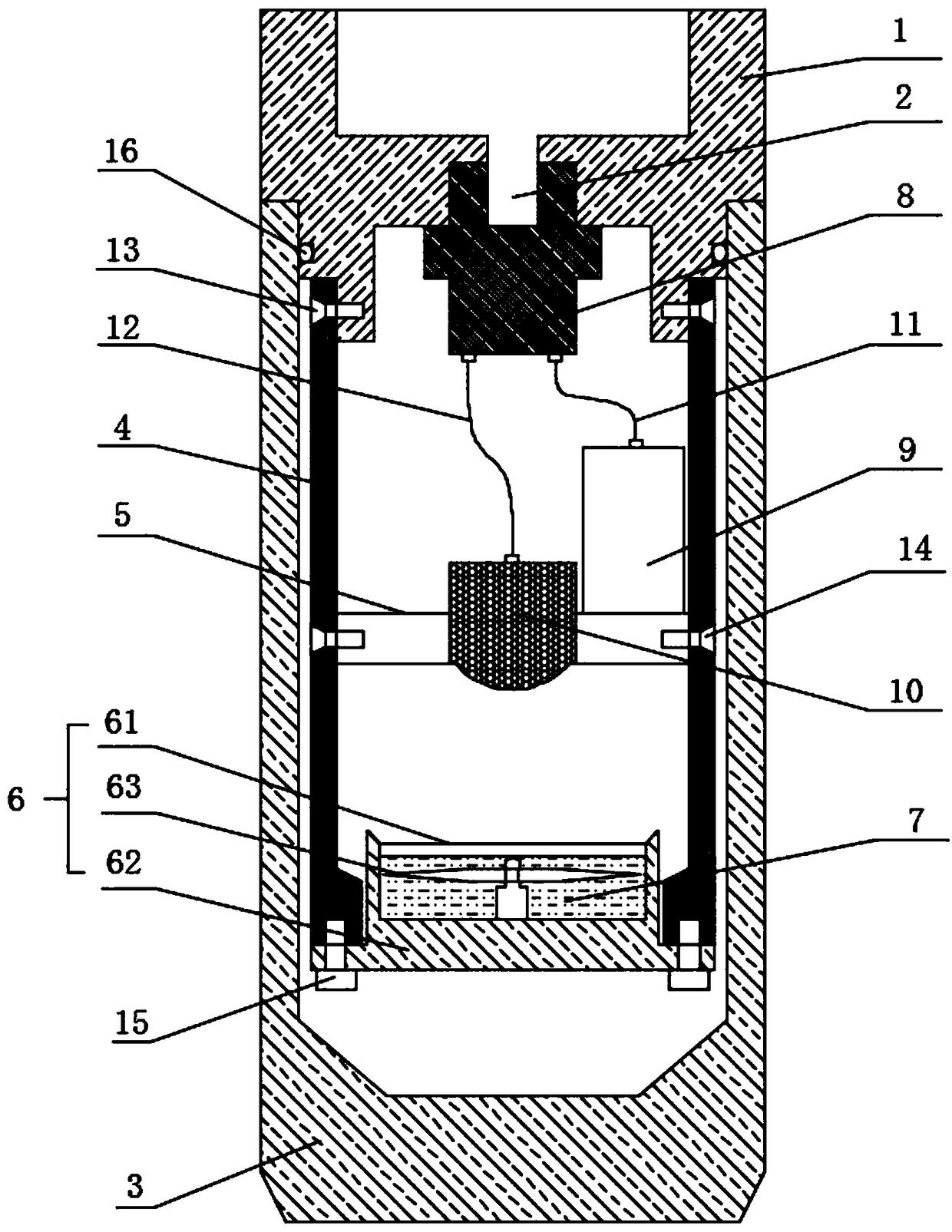
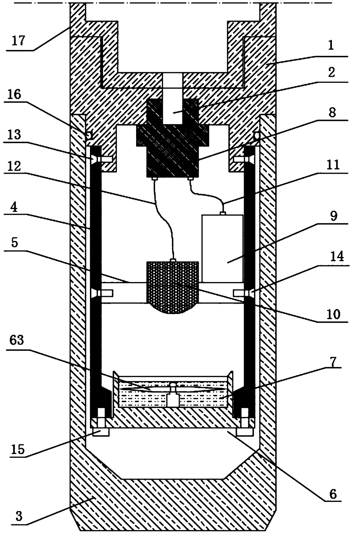
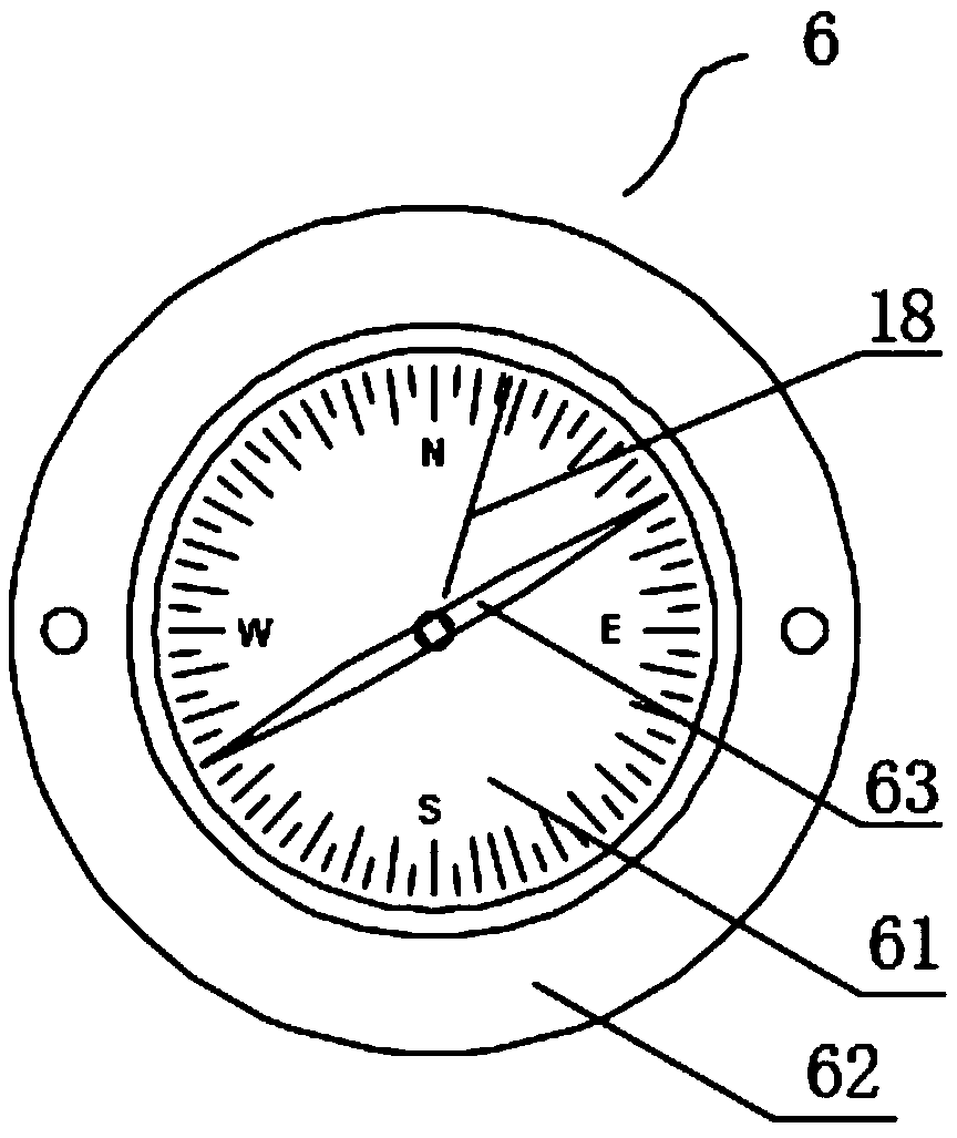
[0019] like figure 1 and figure 2 As shown, a borehole orientation device for hydraulic fracturing ground stress testing provided by the present invention includes a top seat 1 and an outer casing 3, the upper end of the top seat 1 is connected with the lower end of the packer 17 through threads, and the top The lower end of the seat 1 is threadedly connected to the upper end of the outer sleeve 3, and an inner support 4 and a pressure switch 8 are connected to the lower end of the top seat 1. The inner support 4 and the pressure switch 8 are all located inside the outer sleeve 3, and there is also a A battery pack 9, an ultraviolet lamp 10 and a geological compass 6 encapsulated wit...


PUM


Abstract

The invention discloses a direction determining device in a drilling hole for crustal stress testing according to a hydrofracturing method. The device comprises a top base and an outer sleeve. The upper end of the top base is connected with the lower end of a packer through threaded connection. The lower end of the top base is connected with the upper end of the outer sleeve through threaded connection. The lower end of the top base is connected with an inner support and a pressure switch. The inner support and the pressure switch are arranged in the outer sleeve. The outer sleeve is internally provided with a battery, an ultraviolet lamp and a geological compass in which liquid UV glue is packaged. The geological compass is fixed to the lower end of the inner bracket. The battery and theultraviolet lamp are fixed to the middle part of the inner support through a middle separating board. The ultraviolet lamp right faces the dial of the geological compass. The pressure switch is communicated with a pressure hole in the top base. The pressure hole is communicated with the inner chamber of the packer. The battery is connected with the input contact of the pressure switch through a first lead harness. The ultraviolet lamp is connected with the output contact of the pressure switch through a second lead harness. The direction determining device in the drilling hole can resist a measurement error caused by loosening and deflection of a compass pointer because of any vibration interference.

Description

technical field [0001] The invention relates to the technical field of in-situ testing of rock masses, in particular to an in-drilling orienting device for in-situ stress testing by hydraulic fracturing. Background technique [0002] The main stress direction of the hydraulic fracturing ground stress test is obtained by the impression method. The basic working principle is: use the asphaltene colloid on the outer layer of the packer to print the cracks in the drilled rock mass, and use the orientation device at the bottom of the equipment Acquire the azimuth data synchronously, and then determine the specific azimuth of the crack in the rock mass. At present, the orientation devices used for hydraulic fracturing testing mainly adopt several technical solutions such as borehole inclinometer, borehole photography technology and geological compass with locking function. [0003] Among them, the solution using borehole inclinometer and borehole camera technology needs to arrang...

Claims


Application Information

Patent Timeline
Patent Type & Authority Applications(China)
IPC IPC(8): E21B49/00E21B47/02E21B43/26
CPCE21B43/26E21B47/02E21B49/00
Inventor 刘博刘奇罗超文
Owner INST OF ROCK AND SOIL MECHANICS - CHINESE ACAD OF SCI
Why Eureka
Try Eureka