
Fiber grating sensor and method for measuring pressure of shield segment

A fiber grating and shield segment technology, which is applied in the direction of measuring force, measuring the change force of the optical properties of the material when it is stressed, and measuring devices, can solve the problem of inability to directly monitor the water and soil pressure of the segment, and pre-buried The sensor cannot be repaired and replaced, and the accuracy of the test result is reduced, so as to achieve the effects of easy timely control, improved safety and reliability, and convenient maintenance and replacement

Pending Publication Date: 2019-11-19
INST OF ROCK AND SOIL MECHANICS - CHINESE ACAD OF SCI
View PDF0 Cites 1 Cited by
  • Summary
  • Abstract
  • Description
  • Claims
  • Application Information

AI Technical Summary

Problems solved by technology

[0003] After the prefabricated segments are assembled, due to the tightness of the tunnel and the complexity of shield construction, it is impossible to directly monitor the water and soil pressure outside the segments. At present, the water and soil pressure outside the segments is mainly measured by drilling holes from the ground to the vicinity of the segments. Conduct indirect testing or pre-embed stress sensors outside the segment for monitoring, but both methods have disadvantages in the actual application process. The indirect test method causes disturbance to the soil, which reduces the accuracy of the test results. The method of pre-embedded stress sensor monitoring often loses the monitoring function due to damage to the sensor during construction, and once the pre-embedded sensor outside the segment is damaged, it cannot be repaired and replaced

Method used


Image

  • Fiber grating sensor and method for measuring pressure of shield segment
  • Fiber grating sensor and method for measuring pressure of shield segment

Examples


Embodiment Construction

[0029] In order to make the object, technical solution and advantages of the present invention clearer, the present invention will be further described in detail below in conjunction with the accompanying drawings and embodiments. It should be understood that the specific embodiments described here are only used to explain the present invention, not to limit the present invention. In addition, the technical features involved in the various embodiments of the present invention described below can be combined with each other as long as they do not constitute a conflict with each other.

[0030] During the construction of the shield tunnel, in order to ensure the stability of the soil around the tunnel, the grouting hole reserved on the segment is generally used for initial grouting and secondary grouting. After the grouting is completed, the grouting hole will be blocked. , Therefore, once the shield tunnel is built, the grouting hole becomes the only channel connecting the insi...


PUM


Abstract

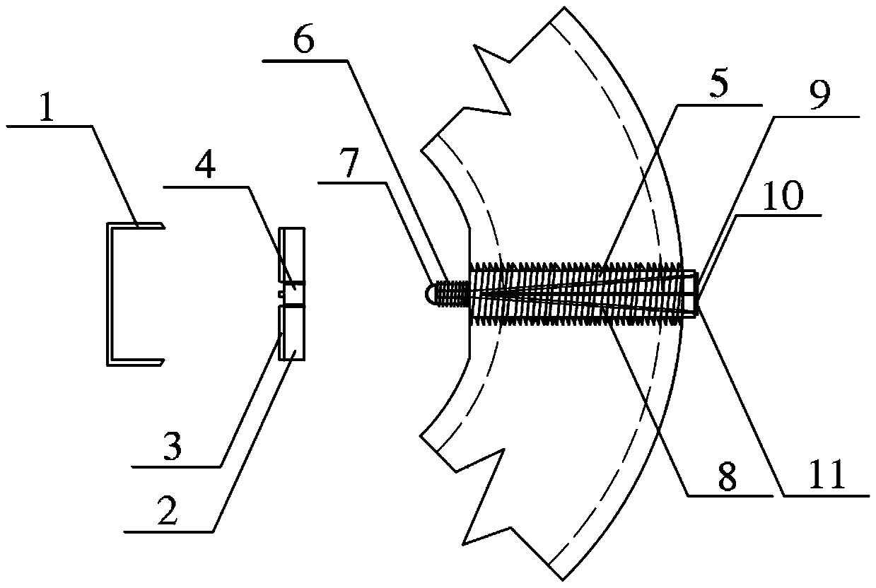
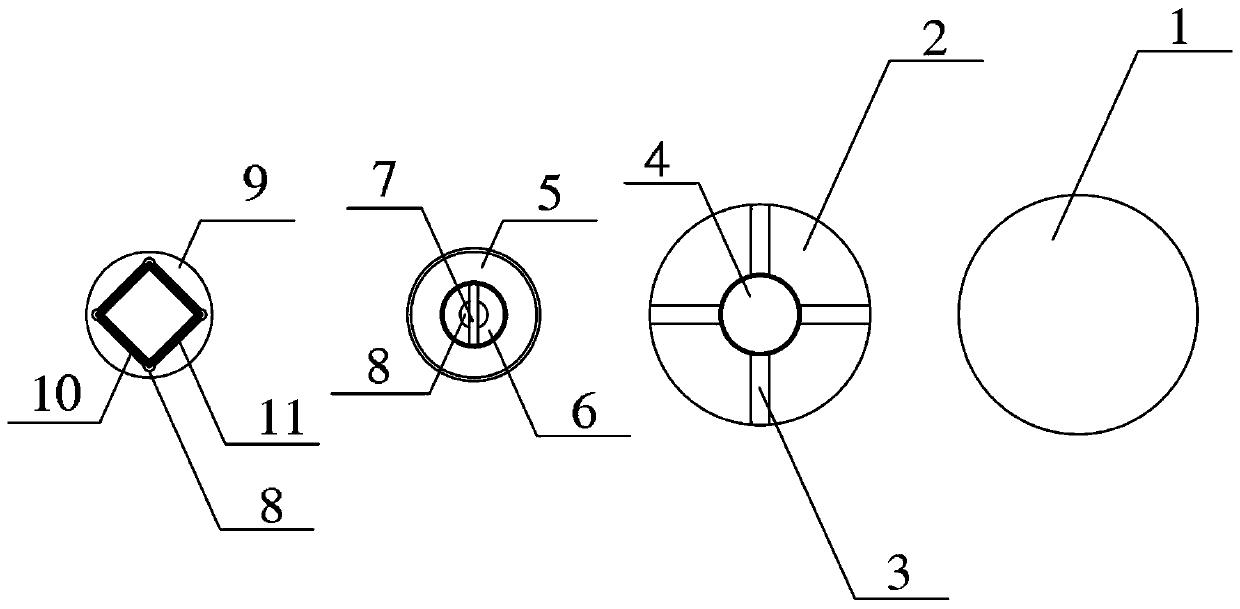
The invention discloses a fiber grating sensor for measuring pressure of a shield segment. The fiber grating sensor includes a grouting hole shaft tube device, an inner ring protection device and an outer ring measurement device; and the grouting hole shaft tube device includes a grouting hole shaft tube (5), the grouting hole shaft tube (5) includes a grouting hole shaft tube segment (6) and a grouting hole shaft tube end section (7), a plurality of reserved holes (9) are disposed inside the grouting hole shaft tube (5), the inner ring protection device includes a steel protection cover (2),a threaded hole (4) is disposed in the center of the steel protection cover (2), and the outer ring measurement device includes a fiber grating (12). The invention also discloses a method for measuring the pressure of the segment. The fiber grating sensor of the invention can accurately measure the water and soil pressure outside the segment, can monitor the water and soil pressure outside the segment during an entire period, an entire interval, and an entire process, provides more comprehensive information outside a tunnel for tunnel construction and operation stages, and can be repaired andreplaced in time once the sensor is damaged,.

Description

technical field [0001] The invention belongs to the technical field of monitoring during the construction period and operation period of tunnel shield tunneling, and more specifically relates to an optical fiber grating sensor and a method for measuring the pressure of shield tunneling segments. Background technique [0002] With the rapid development of my country's underground engineering, especially urban rail transit engineering construction, shield machines have been widely used due to their high efficiency, small disturbance, safety and economy. With the continuous emergence of large-diameter and super-large-diameter tunnels, more and more attention has been paid to the impact of the stress on the tunnel stability after the shield prefabricated segments are assembled. Segment damage due to uneven force, Accidents such as tunnel buoyancy and water gushing between segments threaten the safety of engineering construction. [0003] After the prefabricated segments are ass...

Claims


Application Information

Patent Timeline
Patent Type & Authority Applications(China)
IPC IPC(8): G01L1/24E21D11/08
CPCG01L1/242E21D11/08
Inventor 朱泽奇陈国良盛谦朱付广杨景祥
Owner INST OF ROCK AND SOIL MECHANICS - CHINESE ACAD OF SCI
Learn More