

A construction method of mine seepage well grouting type sinking
A construction method and well seepage technology, which can be used in sinking, mining equipment, earthwork drilling and mining, etc., can solve the problems of unresolved heat of hydration, poor construction quality of the outer wall of the shaft wall, and large thickness of shaft wall support. , to achieve the effect of low concrete grade, small support thickness and controllable quality
Active Publication Date: 2019-10-01
中煤能源研究院有限责任公司
View PDF5 Cites 1 Cited by
- Summary
- Abstract
- Description
- Claims
- Application Information
AI Technical Summary
Problems solved by technology
At present, the freezing method is generally used in the western region. The construction technology of the freezing method is controllable, but the investment is huge. In addition, the thickness of the vertical shaft wall support is very large. The thickness of some mine shaft walls has reached more than two meters. Due to the use of high-grade Concrete, the problem of hydration heat has not been solved, resulting in poor construction quality of the outer wall of the well wall
Method used
View moreImage
Smart ImageViewing Examples

Examples
Embodiment 1
Login to View More PUM
 Abstract
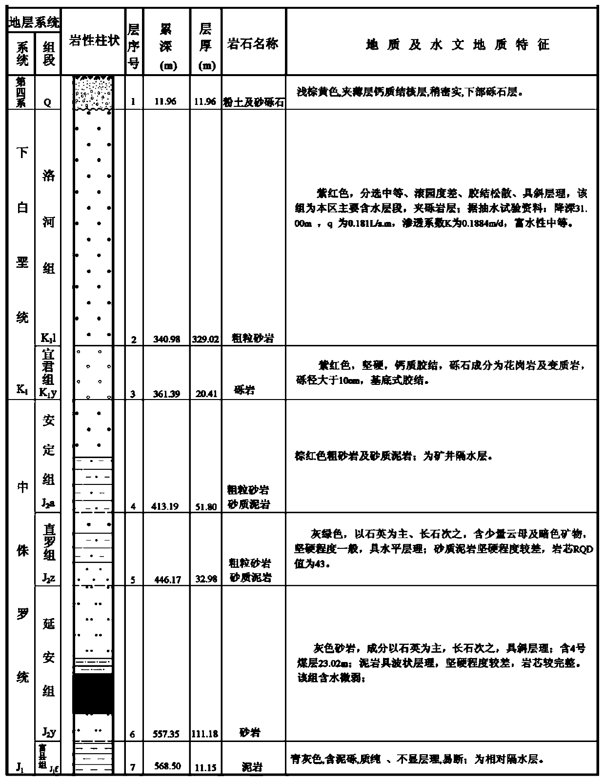
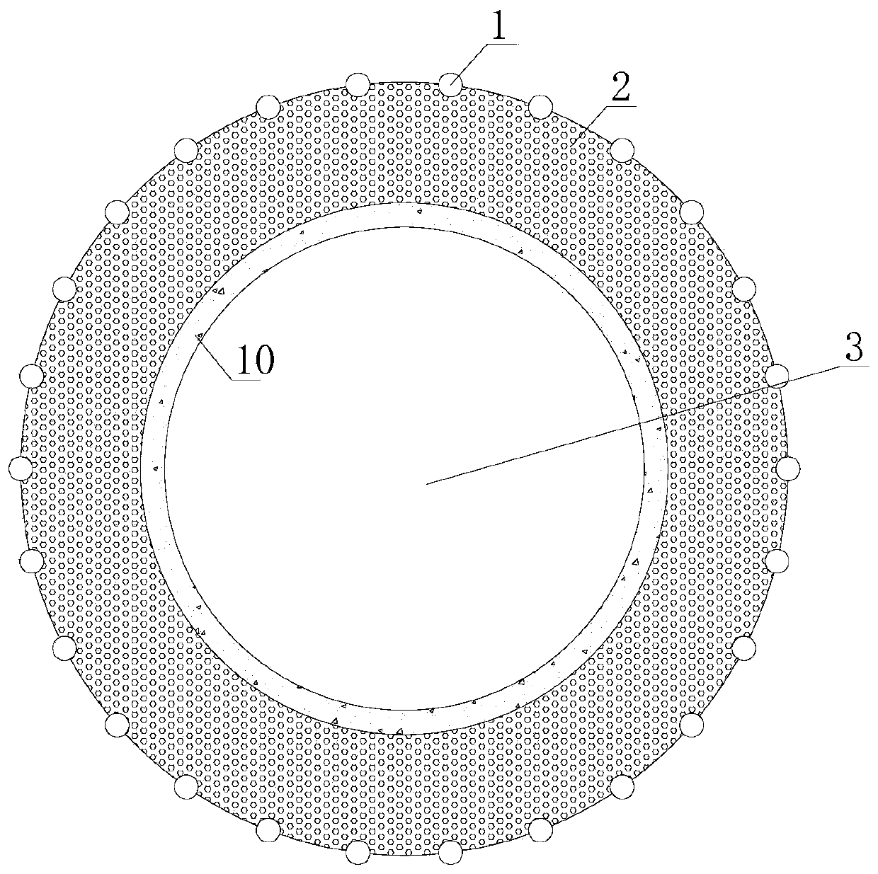
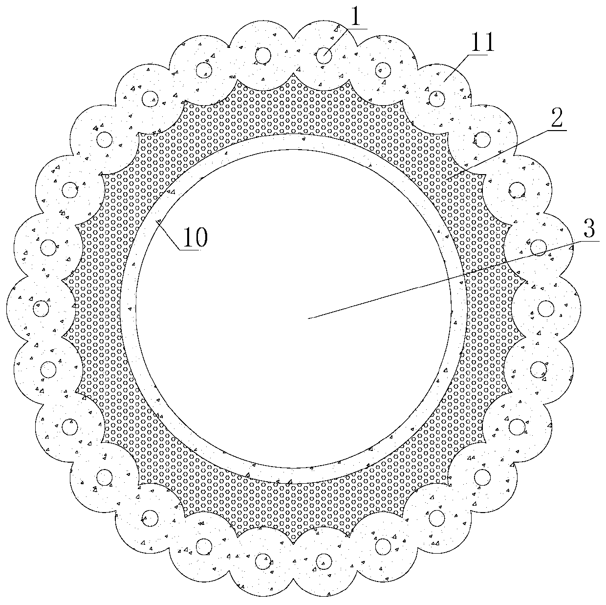
The invention discloses a slurry injection type shaft sinking construction method of a seepage well of a mine. During construction, by use of seepage well principle, water of a target water containinglayer is drained to a to-be-injected water containing layer under the well. A water drainage and pressure releasing driller of an underground roadway or a kilometer directional driller is used for carrying out water drainage and pressure releasing on the water containing layer around a shaft, so a water drainage funnel is formed, an annular water interception well is formed and the shaft is capable of using a common borehole blasting method to carry out dry well operation. After the water containing layer is constructed by the well cylinder, a slurry injection pipe in the seepage well is usedfor carrying out slurry injection blocking on the seepage well and the surrounding rock. According to the invention, water inflow quantity can be reduced by use of a shaft sinking method where construction is performed by use a common method. The provided construction method is suitable for construction of quite big shafts where the water inflow in the later period of the mine.
Description
technical field The invention relates to a construction method of a shaft of a mine vertical shaft, in particular to a construction method of a mine seepage well grouting type sinking well. Background technique Engineering design often encounters geological conditions with a large amount of water gushing out of the shaft shaft. Due to the large amount of water gushing out of the shaft shaft, many mines have to adopt drilling methods such as freezing method and grouting method, which require a large investment. Grouting is divided into ground pre-grouting and working face pre-grouting. Since the aquifer in many areas is pore water, grouting can be performed directly during construction, which cannot guarantee the grouting effect, and is prone to grout leakage and run-out. The investment is also large, and the technology is uncontrollable. It is rarely used in the western region, and there are cases of failure. At present, the freezing method is generally used in the wester...
Claims
Login to View More Application Information
Patent Timeline
 IPC IPC(8): E21D1/10E21D1/06
Inventor 郑忠友刘清宝华召文朱磊丁湘宋立平吴玉意蒲治国李娟王长友郭光乔王洋段东伟贺晓浪
Owner 中煤能源研究院有限责任公司