
Electric locomotive air feeding fan testing tool equipment

A technology for blower fans and electric locomotives, applied in mechanical equipment, machine/engine, pump control, etc., can solve the problems of long procurement cycle and high cost and price of customized equipment, and achieve strong promotion and application value, strong practicability, and novel design Effect

Pending Publication Date: 2018-12-18
CRRC LUOYANG CO LTD
View PDF0 Cites 0 Cited by
  • Summary
  • Abstract
  • Description
  • Claims
  • Application Information

AI Technical Summary

Problems solved by technology

Since this type of fan is an imported component, there is no corresponding test equipment in China. If it is purchased from abroad, not only the procurement cycle of customized equipment is long, but also the cost of importing from abroad is high.

Method used


Image

  • Electric locomotive air feeding fan testing tool equipment
  • Electric locomotive air feeding fan testing tool equipment
  • Electric locomotive air feeding fan testing tool equipment

Examples


Embodiment Construction

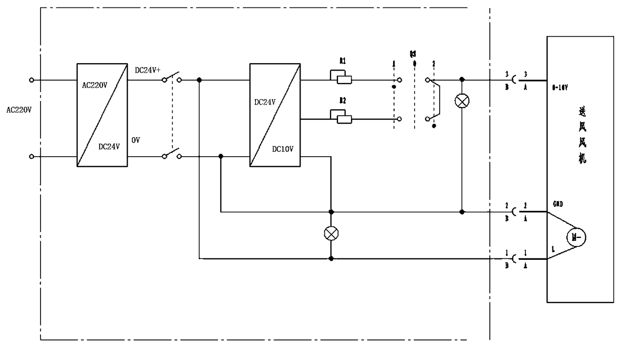
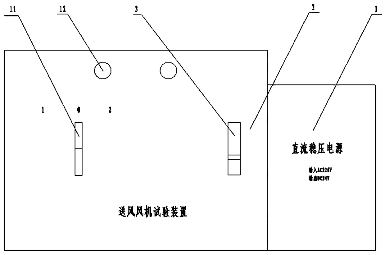
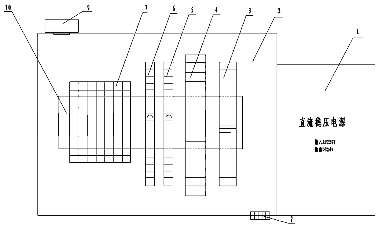
[0020] Numbers in the figure, number 1 stands for DC regulated power supply, number 2 stands for test tooling module, number 3 stands for control switch, number 4 stands for terminal power module, number 5 and 6 represent terminal adjustable resistors, number 7 stands for input terminal block The structure, the number 8 represents the terminal block structure, the number 9 represents the connector structure, the number 10 represents the installation guide rail, the number 11 represents the conversion control switch, and the number 12 represents the status indicator light.

[0021] The present invention will be described in further detail below in conjunction with the accompanying drawings and technical solutions, and the implementation of the present invention will be described in detail through preferred embodiments, but the implementation of the present invention is not limited thereto.

[0022] In view of the high cost, long period, and inconvenient operation in the maintena...


PUM


Abstract

The invention relates to the technical field of locomotive repair, in particular to electric locomotive air feeding fan testing tool equipment. The electric locomotive air feeding fan testing tool equipment comprises a testing tool module and a power supply module. The power supply module comprises a power supply conversion circuit. The testing tool module comprises a casing and a speed control circuit. A conversion control switch, a terminal type power supply module, terminal type adjustable resistors, a control switch and a status indicating lamp are arranged in the speed control circuit. Aregulated DC power supply connected with the testing tool module is converted into dual-path power supply output through the terminal type power supply module. A dual-path power supply output circuitis provided with the terminal type adjustable resistors in sequence, and all the terminal type adjustable resistors are electrically connected with the conversion control switch for controlling the rotating speed of an air feeding fan. The electric locomotive air feeding fan testing tool equipment is simple in structure, novel and reasonable in design, strong in practicability, convenient to carryand strong in popularization and application value. Performance tests can be carried out after component disassembly. After a quality problem is found, fault judging, processing and repairing can beconveniently performed. The repair efficiency is effectively improved.

Description

technical field [0001] The invention relates to the technical field of locomotive repair, in particular to an electric locomotive air supply fan test tooling equipment. Background technique [0002] With the continuous accumulation of technology in the railway field in our country, the harmonious AC drive electric locomotive has developed rapidly in our country and is gradually replacing the existing DC drive electric locomotive. The introduction of advanced technology in the railway field and independent innovation have enabled a large number of imported components with excellent performance and reliability to be adopted by Harmony AC drive electric locomotives. With the increase of the service mileage and service life of Harmony AC drive electric locomotives, the service mileage of early-invested locomotives has exceeded 1.8 million kilometers, and the service time has exceeded 10 years. Overhaul of locomotives), and this part of imported parts introduced and used on loco...

Claims


Application Information

Patent Timeline
IPC IPC(8): F04D27/00
CPCF04D27/001
Inventor 韩松波杨晓梅刘阳朱琳
Owner CRRC LUOYANG CO LTD
Learn More