Heat pipe air conditioning device

An air-conditioning device and heat pipe technology, which is applied in air-conditioning systems, household heating, heating methods, etc., can solve the problems of uneven distribution of compressor refrigeration oil, system failure, and failure to achieve backup, etc., to achieve good energy-saving effects and improve Cooling efficiency, effect of improving efficiency

Pending Publication Date: 2018-12-18
BEIJING FULLLINK OREITH TECH CO LTD
View PDF21 Cites 3 Cited by
  • Summary
  • Abstract
  • Description
  • Claims
  • Application Information

AI Technical Summary

Problems solved by technology

However, there is also a major problem in the air-conditioning mode that uses this heat pipe system and the conventional mechanical compression refrigeration air-conditioning joint operation: if a single compressor is used for cooling, the system cannot be backed up; if dual compressors are used for cooling, it will cause compression. The uneven distribution of machine oil in the freezer will cause damage to the compressor and fail to achieve the effect of backup

Method used


Image

  • Heat pipe air conditioning device
  • Heat pipe air conditioning device
  • Heat pipe air conditioning device

Examples


specific Embodiment approach 1

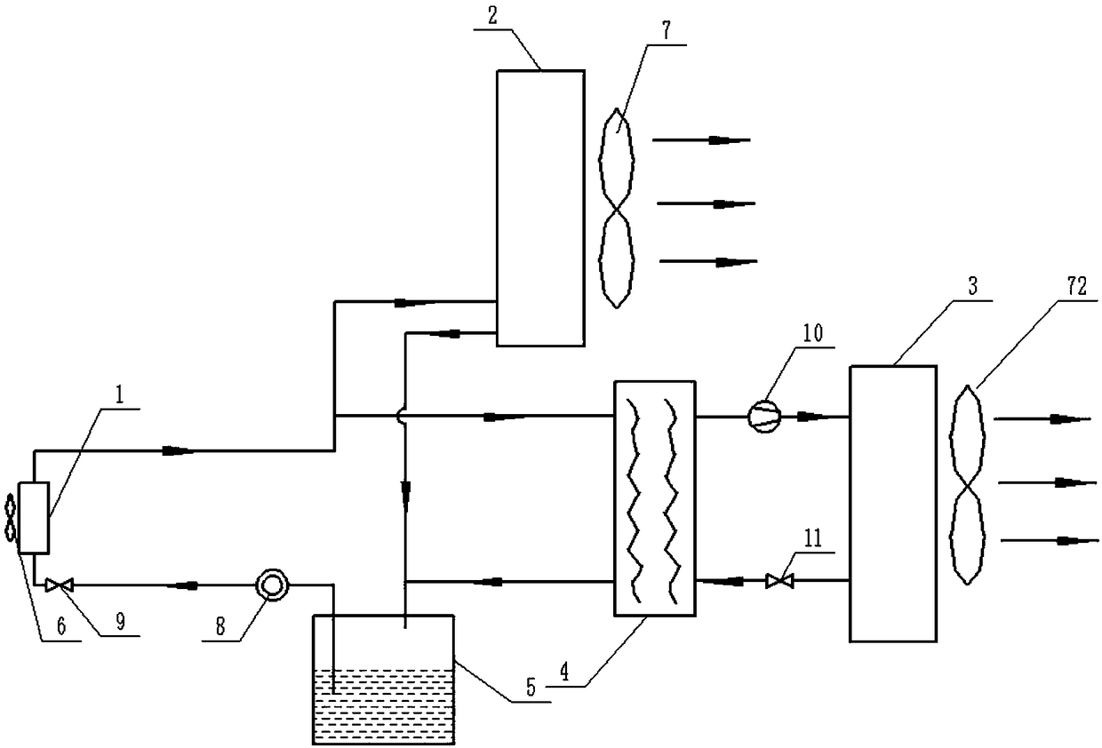
[0026] Please refer to figure 1 The shown heat pipe air conditioner of the present invention includes a heat pipe terminal system, a liquid storage tank 5, a circulation pump 8, a cold source system, a temperature sensor and a control module. The inlet of the circulating pump 8 is connected with the liquid storage tank 5, and the inlet goes deep into the bottom of the liquid storage tank 5; the outlet of the circulating pump 8 is connected with the inlet of the heat pipe end system, and the outlet of the heat pipe end system is connected with the cold source system. The inlet is connected; the outlet of the cold source system is connected with the liquid storage tank 5 .

[0027] The heat pipe end system includes a heat pipe evaporator 1, an evaporator fan 6 and a second electronic expansion valve 9, the second electronic expansion valve 9 is connected to the inlet of the heat pipe evaporator 1; The side is used to promote the heat exchange between the indoor air and the heat...

specific Embodiment approach 2

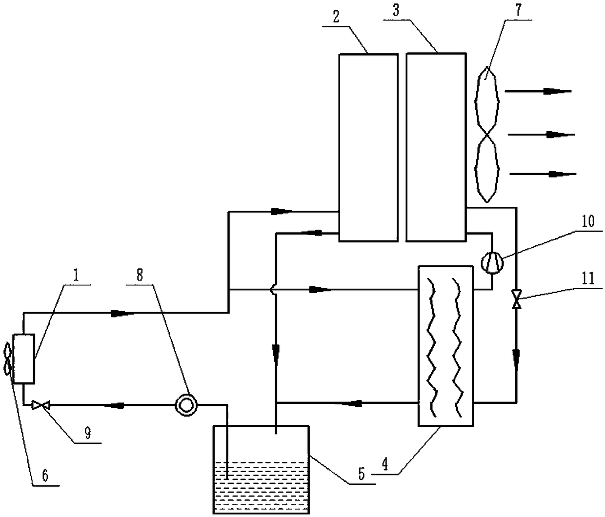
[0041] Please refer to figure 2 As shown, in this embodiment, the heat pipe condenser 2 of the natural cold source and the compressor condenser 3 of the compressor cold source share a condenser fan 7, and the compressor condenser 3 and the heat pipe condenser 2 are placed side by side to condense The condenser fan 7 is installed on one side of the compressor condenser 3, and the wind direction is from the heat pipe condenser 2 to the compressor condenser 3, so that the outdoor air passes through the heat pipe condenser 2 and the compressor condenser 3 to exchange heat with it. All the other parts are the same as the first embodiment, and the working method is also the same.

specific Embodiment approach 3

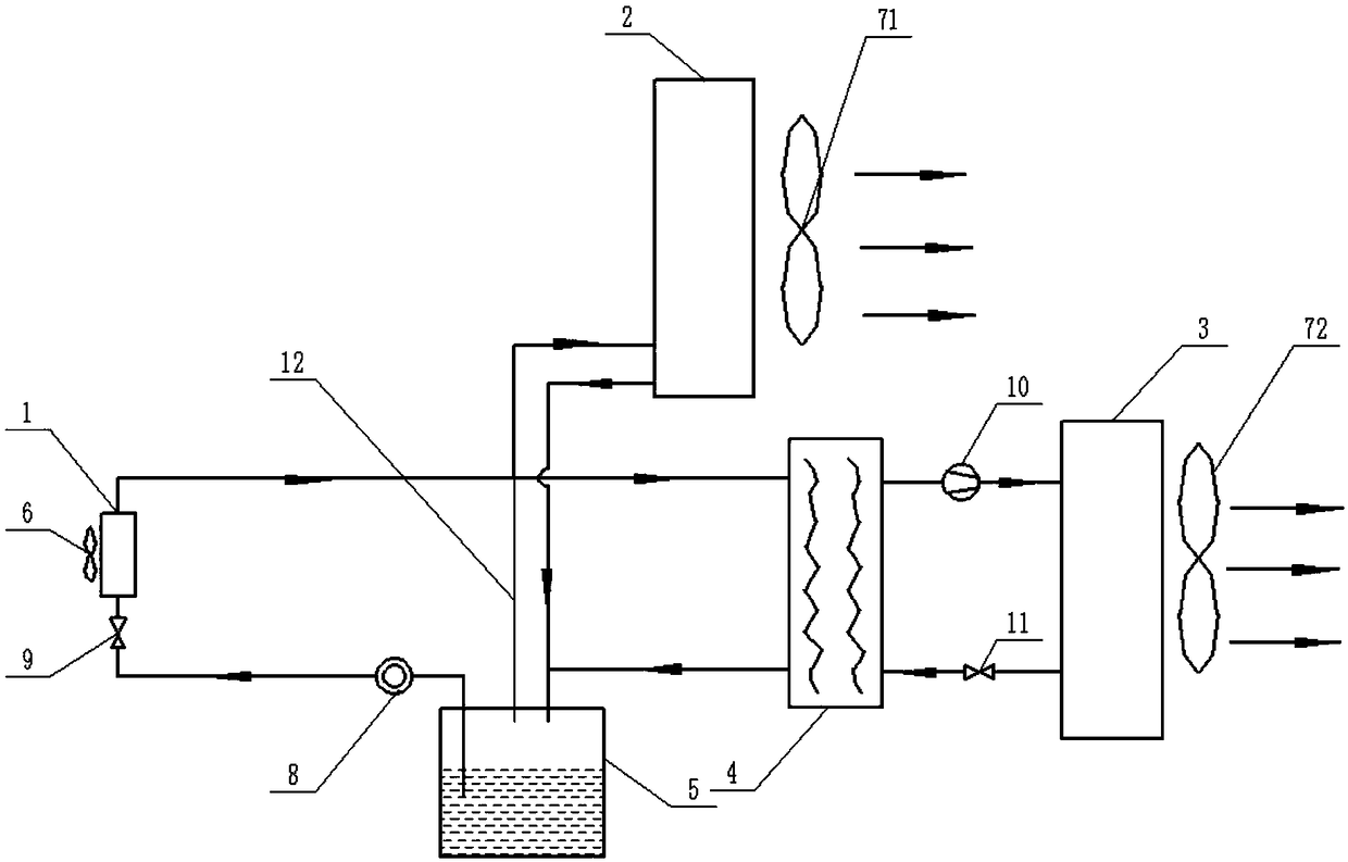
[0042] Please refer to image 3 As shown, in this embodiment, the inlets of the heat pipe condenser 2 of the natural cold source and the intermediate heat exchanger 4 of the compressor cold source system are provided with a balance pipe 12 that communicates with the liquid storage tank 5, Or the heat pipe condenser 2 of the natural cold source and the intermediate heat exchanger 4 heat pipe pipelines of the compressor cold source system are connected in parallel, and a balance pipe 12 connected with the liquid storage tank 5 is provided at the common inlet. On the one hand, the balance pipe 12 is used to make the heat pipe condenser 2 of the natural cold source and the intermediate heat exchanger 4 of the compressor cold source system equal to the pressure difference between the inlet and the outlet of the heat pipe pipeline, and the liquid refrigerant produced during the condensation process It can smoothly return to the liquid storage tank through gravity; on the other hand,...


PUM


Abstract

A heat pipe air conditioning device comprises a heat pipe tail end system, a liquid storage tank, a circulation pump, a cold source system, a temperature sensor and a control module; an inlet of the circulation pump communicates with the liquid storage tank; an outlet of the circulation pump communicates with an inlet of the heat pipe tail end system; an outlet of the heat pipe tail end system communicates with an inlet of the cold source system; an outlet of the cold source system communicates with the liquid storage tank; the heat pipe tail end system comprises a heat pipe evaporator and a second electronic expansion valve; the second electronic expansion valve is connected to an inlet of the heat pipe evaporator; the temperature sensor is used for detecting the humidity difference inside and outside a machine room; and a signal input end of the control module is connected with a signal output end of the temperature sensor, and the control module controls operation of the heat pipe air conditioning device according to signals transmitted and recorded by the temperature sensor.

Description

technical field [0001] The present application relates to the technical field of refrigeration and air conditioning, in particular to a heat pipe air conditioning device. Background technique [0002] With the rapid development of my country's communication industry, the energy consumption and energy-saving problems of the computer room need to be solved urgently, and the new technology of using heat pipe technology in the air-conditioning and energy-saving of the communication computer room and the information center computer room, with its high efficiency, energy saving and green environmental protection, has triggered Widespread concern. [0003] However, the cooling capacity of the heat pipe system is easily affected by the outdoor temperature of the computer room. When the outdoor temperature of the computer room is higher, the cooling capacity of the heat pipe system will be worse, that is, the temperature in the computer room that the heat pipe system can reduce is sma...

Claims


Application Information

Patent Timeline
Patent Type & Authority Applications(China)
IPC IPC(8): F24F5/00F24F13/30
CPCF24F5/0007F24F13/30
Inventor 孙继东丁式平何慧丽杨赢喜张贺
Owner BEIJING FULLLINK OREITH TECH CO LTD
Why Eureka
Try Eureka