In-situ tensile experiment device for scanning electron microscope

A technology of in-situ stretching and scanning electron microscopy, applied to measuring devices, using stable tension/pressure to test material strength, instruments, etc., can solve the problems of less experimental data and inconvenient use

Active Publication Date: 2018-12-18
INNER MONGOLIA UNIV OF TECH
View PDF6 Cites 2 Cited by
  • Summary
  • Abstract
  • Description
  • Claims
  • Application Information

AI Technical Summary

Problems solved by technology

[0002] At present, in the tensile test, usually only the tensile test can be performed on the plate, and the position of the scanning electron microscope is fixed, and the experimental data obtained in the experiment is less, so it is more inconvenient to use

Method used


Image

  • In-situ tensile experiment device for scanning electron microscope
  • In-situ tensile experiment device for scanning electron microscope
  • In-situ tensile experiment device for scanning electron microscope

Examples


Embodiment Construction

[0014] In order to make the purpose, technical solutions and advantages of the embodiments of the present invention clearer, the technical solutions in the embodiments of the present invention will be clearly and completely described below in conjunction with the drawings in the embodiments of the present invention. Obviously, the described embodiments It is a part of embodiments of the present invention, but not all embodiments. Based on the embodiments of the present invention, all other embodiments obtained by persons of ordinary skill in the art without creative efforts fall within the protection scope of the present invention.

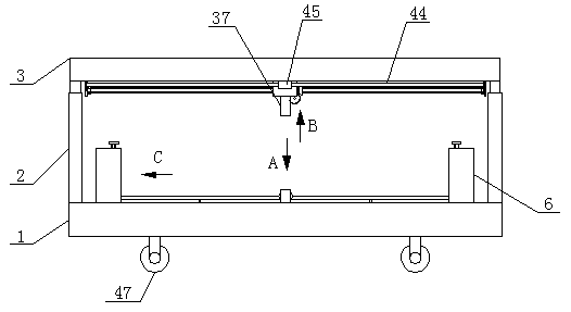
[0015]The in-situ tensile test device for the scanning electron microscope, as shown in the figure, includes a base 1, the four corners of the top surface of the base 1 are respectively fixed with vertical lifting rods 2, and the tops of the four lifting rods 2 are fixedly connected by a square block 3 , the square block 3 and the base 1 are paral...


PUM


Abstract

The invention provides an in-situ tensile experiment device for a scanning electron microscope. The in-situ tensile experiment device comprises a base; vertical lifting rods are fixedly installed at the four corners of the top face of the base respectively, the top ends of the four lifting rods are fixedly connected through a square block, and the square block and the base are mutually parallel; guiding grooves are formed in the front end and the back end of the top face of the base respectively, two guiding blocks are arranged in each guiding groove in a matched mode, and every two guiding blocks which are located on the same side of the base are fixedly connected through a long strip block; and the two long strip blocks are mutually parallel, long strip-shaped grooves are formed in the opposite faces of the two long strip blocks respectively, three movable blocks are arranged in each groove in a matched mode, and the three movable blocks located in the same groove are arranged sequentially from front to back. A fourth nut and a ball bearing are fixedly connected through a connecting rod, a second bevel gear is fixedly connected with the inner ring of the ball bearing, then the second bevel gear can be driven to move when the fourth nut moves, and therefore a moving block can do horizontal reciprocating motion.

Description

technical field [0001] The invention belongs to the field of mechanical devices, in particular to an in-situ tensile test device for a scanning electron microscope. Background technique [0002] At present, in the tensile test, usually only the tensile test can be performed on the plate, and the position of the scanning electron microscope is fixed, and the experimental data obtained in the experiment is less, so it is inconvenient to use. Contents of the invention [0003] The invention provides an in-situ stretching test device for a scanning electron microscope, which is used to solve the defects in the prior art. [0004] The present invention is achieved through the following technical solutions: [0005] The in-situ tensile test device for scanning electron microscope includes a base, and the four corners of the top surface of the base are respectively fixed with vertical lifting rods, and the tops of the four lifting rods are fixedly connected by a square block. G...

Claims


Application Information

Patent Timeline
Patent Type & Authority Applications(China)
IPC IPC(8): G01N3/08G01N3/02
CPCG01N3/02G01N3/08G01N2203/0017
Inventor 李继军李士杰金永军邢永明张伟光郎风超侯小虎
Owner INNER MONGOLIA UNIV OF TECH
Why Eureka
Try Eureka