Industrial CT detection system

A detection system and industrial technology, applied in measurement devices, instruments, scientific instruments, etc., can solve the problems of low utilization rate and inconvenient movement of industrial CT, and achieve the effect of improving utilization rate, reducing mobile costs, and improving mobility

Inactive Publication Date: 2018-12-18
中国人民解放军96630部队 +1
View PDF11 Cites 1 Cited by
  • Summary
  • Abstract
  • Description
  • Claims
  • Application Information

AI Technical Summary

Problems solved by technology

[0005] The purpose of the present invention is to provide an industrial CT detection system to solve the problems of inconvenient movement and low utilization rate of existing industrial CTs

Method used


Image

  • Industrial CT detection system
  • Industrial CT detection system
  • Industrial CT detection system

Examples


Embodiment 1

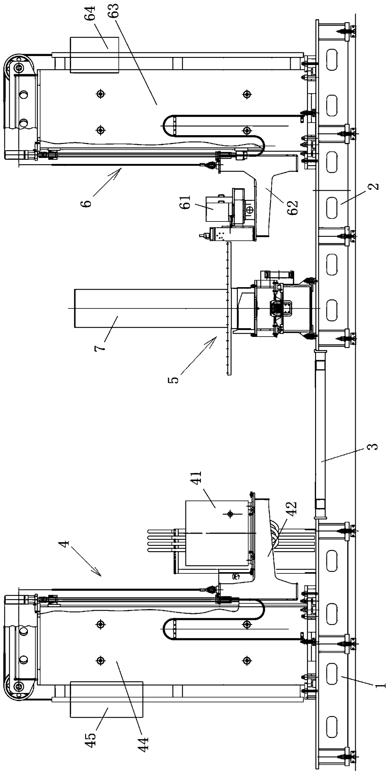
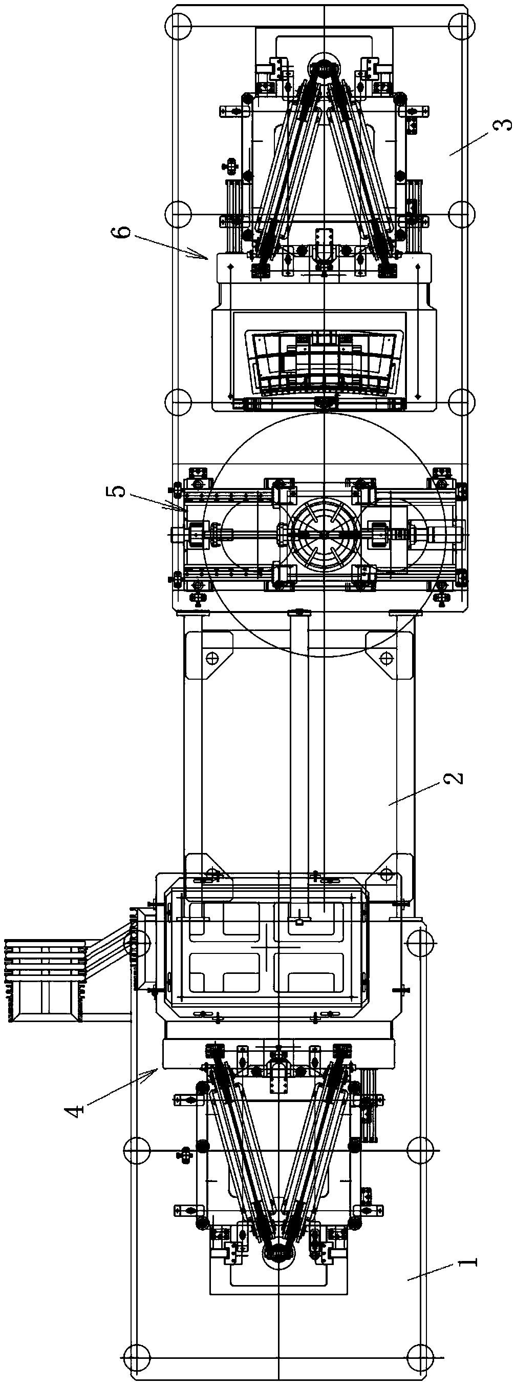
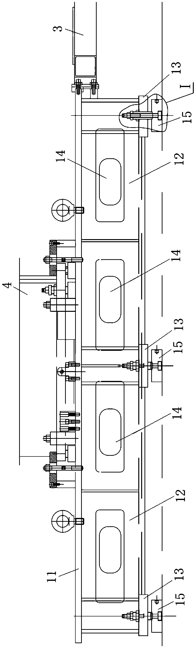
[0032] Such as figure 1 with figure 2 As shown, the industrial CT detection system includes a first installation platform 1, a second installation platform 2, a platform connection frame 3, a radiation source 4, a turntable 5 and a detector unit 6, and the first installation platform 1 and the second installation platform 2 are fixedly connected At two opposite ends of the platform connecting frame 3, and make the upper surfaces of the first installation platform 1 and the second installation platform 2 be in the same plane. The radiation source 4 is fixed on the upper surface of the first installation platform 1 , and the turntable 5 and the detector unit 6 are fixed on the upper surface of the second installation platform 2 . In other words, the platform connection frame 3 fixedly connects the first installation platform 1 and the second installation platform 2 together, so that the first installation platform 1 and the second installation platform 2 are integrated, which ...


PUM


Abstract

The invention discloses an industrial CT detection system. The system comprises a ray source, a rotary table and a detector unit; the ray source and the detector unit are arranged on the opposite sides of the rotary table respectively; the system further comprises a first mounting platform, a second mounting platform and a platform connecting frame; the first mounting platform and the second mounting platform are fixedly connected to the two opposite ends of the platform connecting frame, and the upper surfaces of the first mounting platform and the second mounting platform are located on thesame plane; the ray source is fixed on the upper surface of the first mounting platform; and the rotary table and the detector unit are fixed on the upper surface of the second mounting platform. Theindustrial CT detection system is enhanced in mobility, low in moving cost and high in utilization rate.

Description

technical field [0001] The invention relates to the technical field of industrial detection, in particular to an industrial CT detection system. Background technique [0002] Industrial CT is the abbreviation of industrial computerized tomography technology, which is a technology developed on the basis of radiation detection. When collimated and the energy is I 0 When the ray beam passes through the detected object, according to the different attenuation coefficients of each volume element in each transmission direction, the transmission energy I received by the detector is different. According to a certain image reconstruction algorithm, a tomographic image of the cross-section of the inspected workpiece - a thin layer without overlapping images is obtained, and a new tomographic image can be obtained by repeating the above process. When enough two-dimensional tomographic images are measured, a three-dimensional tomographic image can be reconstructed image. In other word...

Claims


Application Information

Patent Timeline
Patent Type & Authority Applications(China)
IPC IPC(8): G01N23/046
CPCG01N23/046
Inventor 路廷镇苏志军薛海峰贾庆龙薛冰刘利华杨明李俊江
Owner 中国人民解放军96630部队
Why Eureka
Try Eureka