Laser radar emitting device and method

A laser radar and launcher technology, applied in the field of detection, can solve the problems of unfavorable laser radar miniaturization, long distance between the rotating scanning device and the laser, increasing the volume of the laser radar launcher, etc.

Inactive Publication Date: 2018-12-18
北京大汉正源科技有限公司
View PDF7 Cites 12 Cited by
  • Summary
  • Abstract
  • Description
  • Claims
  • Application Information

AI Technical Summary

Problems solved by technology

However, the lidar usually contains multiple lasers, and the beams emitted by each laser have a certain angle. In order to reduce the volume and quality of the lidar rotating scanning device and improve the scanning speed, the rotating scanning device is usually installed on each beam The position of the intersection point, which results in a longer distance between the rotating scanning device and the laser, thereby increasing the volume of the laser radar transmitter, which is not conducive to the miniaturization of the laser radar

Method used


Image

  • Laser radar emitting device and method
  • Laser radar emitting device and method
  • Laser radar emitting device and method

Examples


Embodiment Construction

[0025] A laser radar transmitting device and a transmitting method of the present invention will be described below with reference to the embodiments.

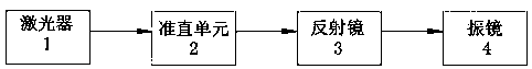
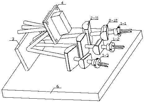
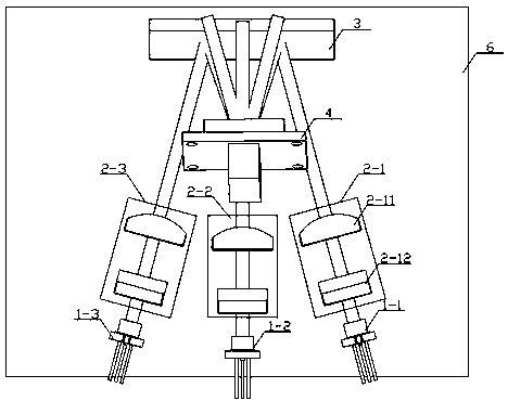
[0026] A laser radar transmitting device and a transmitting method of the present invention, such as figure 1 As shown, it includes a laser 1 for emitting laser light; a collimation unit 2 for collimating the laser beam to compress the divergence angle of the laser beam; it is arranged on the transmission path of the collimated laser beam for changing the transmission direction of the laser beam Furthermore, the reflection mirror 3 that changes the intersection position of the laser beam; the vibrating mirror 4 that is arranged at the intersection position of the laser beam and is used to change the outgoing angle of the laser beam. The reflector 3 changes the transmission direction of the laser beam, thereby changing the intersection position of the laser beam and changing the setting position of the vibrating mirror 4, there...


PUM


Abstract

The invention relates to a laser radar emitting device and method. The laser radar emitting device comprises at least two laser devices used for emitting laser, a reflector used for changing a transmission direction of laser beams emitted by the laser devices to change an intersection point position of the laser beams, and a galvanometer arranged in the intersection point position of the laser beams and used for changing an emergence angle of the laser beams, wherein an included angle is formed between the laser beams emitted by the laser devices. The reflector can change the transmission direction of the laser beams to change the intersection point position of the laser beams, and the arrangement position of the galvanometer is changed, so that the linear distances between the laser devices and the galvanometer are reduced, and then the size of the laser emitting device is reduced.

Description

technical field [0001] The invention relates to the technical field of detection, in particular to a laser radar transmitting device and a transmitting method. Background technique [0002] The field of unmanned driving has recently attracted people's attention. The reliability and safety of unmanned vehicles are related to the safety of people's lives. Install lidar on driverless cars. Using TOF principle, lidar can detect nearby objects and measure the distance of objects during the driving process of the car, so as to control the driving route of the vehicle and the stop and start of the vehicle through the control module of the vehicle. [0003] The principle of TOF is to emit a beam of high-power pulsed laser, hit it on the object to be measured, and calculate the distance by measuring the time difference between the emission time and the reception time. Lidar is usually composed of a laser transmitter and a laser receiver. By installing the laser radar on the driverle...

Claims


Application Information

Patent Timeline
Patent Type & Authority Applications(China)
IPC IPC(8): G01S7/481G01S7/484
CPCG01S7/4814G01S7/484
Inventor 刘定刘峰
Owner 北京大汉正源科技有限公司
Why Eureka
Try Eureka