
Extremely low frequency and magnetotelluric joint measurement method

A magnetotelluric and measurement method technology, applied in geophysical measurement, electromagnetic wave detection, radio wave measurement system, etc., can solve problems such as defect influence and poor data quality, and achieve the effect of improving observation quality

Inactive Publication Date: 2018-12-18
INST OF GEOLOGY & GEOPHYSICS CHINESE ACAD OF SCI
View PDF5 Cites 15 Cited by
  • Summary
  • Abstract
  • Description
  • Claims
  • Application Information

AI Technical Summary

Problems solved by technology

[0002] When detecting geological structures at a depth of 10km, the commonly used electromagnetic exploration method is the magnetotelluric sounding method (MT). The magnetotelluric sounding method uses natural field signals, and its observation frequency is 0.001Hz to 320Hz. The electromagnetic field signal is affected by the extremely weak "dead frequency band" of the natural field electromagnetic field from 0.1Hz to 1Hz, which makes the data quality observed by MT in this frequency band poor. Due to the defect in the quality of this frequency data, MT has affected the geological analysis of the nearly 10km deep formation. structure detection

Method used


Image

  • Extremely low frequency and magnetotelluric joint measurement method
  • Extremely low frequency and magnetotelluric joint measurement method
  • Extremely low frequency and magnetotelluric joint measurement method

Examples


Embodiment Construction

[0034] The specific embodiment of the present invention is described below in conjunction with accompanying drawing:

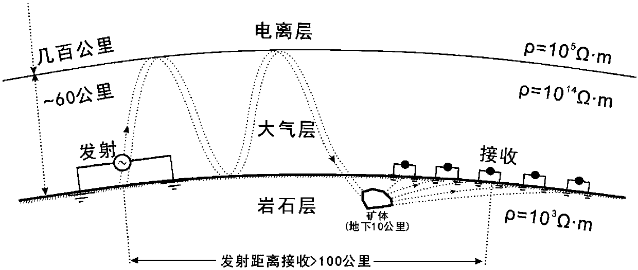
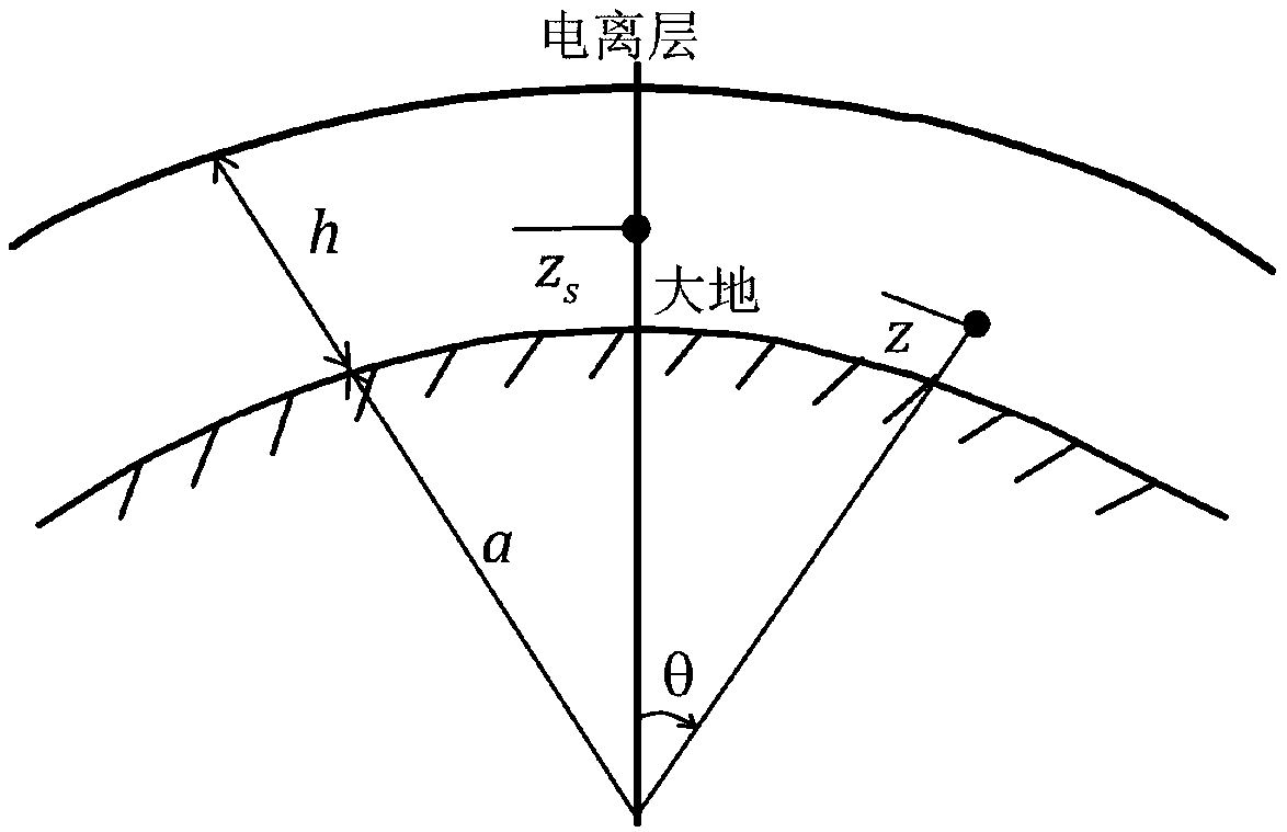
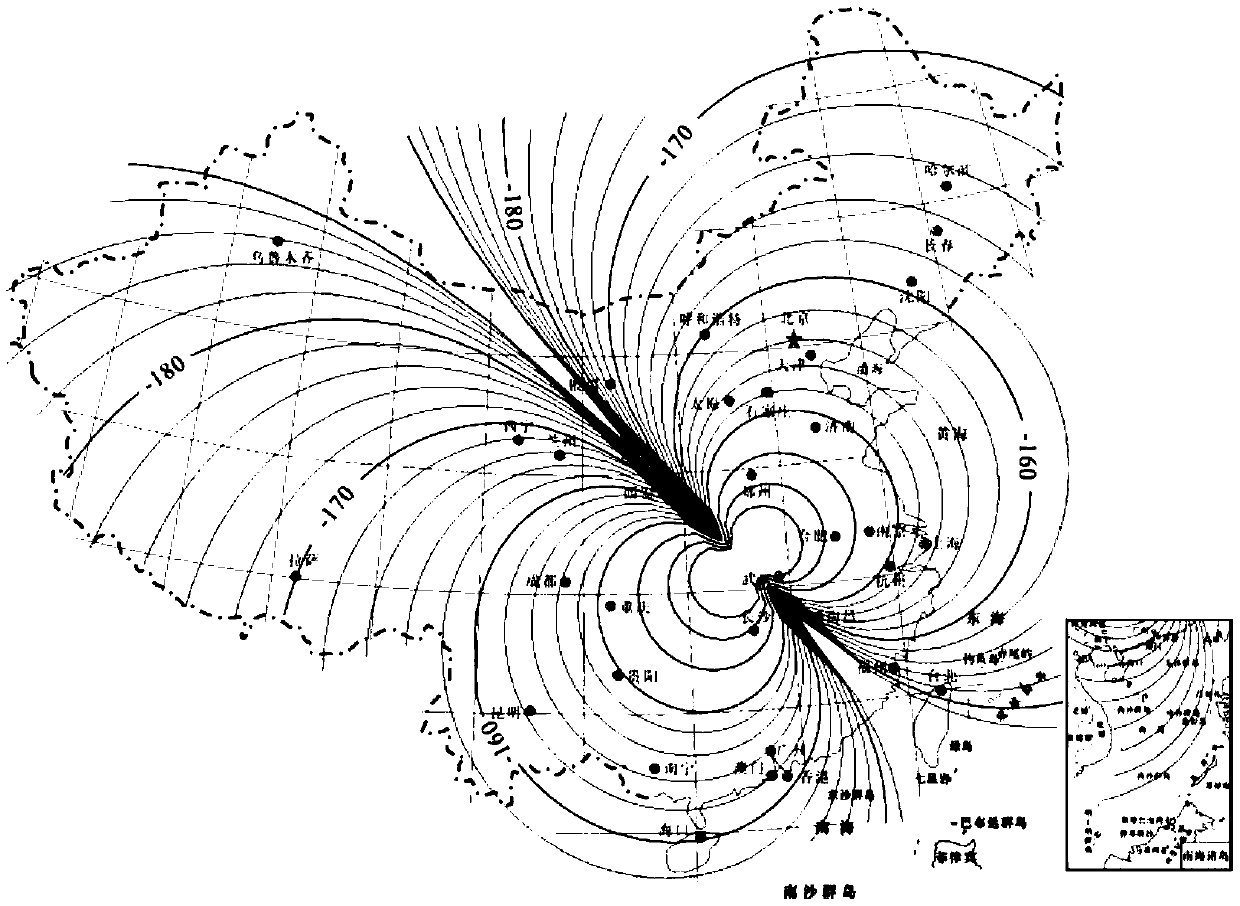
[0035] The WEM method is an artificial source electromagnetic method. Its principle is similar to that of the CSAMT method, that is, an electromagnetic signal is transmitted through an artificial source and the signal is received at a certain distance from the source. The difference is that the WEM method establishes a fixed high-power emission source, the signal covers the whole country, and the signal-to-noise ratio reaches 10dB-20dB. It not only has the characteristics of large detection depth and low cost of the MT method, but also has the artificial source electromagnetic method (CSAMT, etc.) With the characteristics of strong anti-interference ability and high detection accuracy, it is a new method and technology for underground resource detection and seismic and geomagnetic monitoring.

[0036] The signal of the WEM method injects electromagnetic waves ...


PUM


Abstract

The invention discloses an extremely low frequency and magnetotelluric joint measurement method, and belongs to the technical field of deep resource detection. The extremely low frequency and magnetotelluric joint measurement method is specifically used for precise detection of deep geological formation and construction, and can be especially used for the detection of high-resolution electrical fine structures in deep 10km of oil and gas fields. The extremely low frequency and magnetotelluric joint measurement method is as follows: an electromagnetic wave is obtained by using a signal emissionsource of a WEM method, that is, variable frequency current is injected into the underground through a large emission power source, the generated electromagnetic wave is propagated upward to form a sky wave, the sky wave is propagated to an ionized layer, then is reflected by the ionized layer to an underground ore body and finally is propagated by an underground medium to the ground; and an array type WEM electromagnetic signal and an MT natural field electromagnetic signal are received in an oil and gas field, and a high-resolution electrical fine structure in the deep oil and gas field isobtained by joint measurement and data processing inversion interpretation of the WEM electromagnetic signal and the MT natural field electromagnetic signal. By adoption of the extremely low frequencyand magnetotelluric joint measurement method disclosed by the invention, the prediction precision of residual basin distribution in the ultra-deep mesoproterozoic erathem and neoproterozoic erathem can be improved, and a scientific basis is provided for the assessment of oil and gas resources within the depth range.

Description

technical field [0001] The invention specifically relates to an extremely low frequency and magnetotelluric joint measurement method, which belongs to the technical field of deep resource detection. It is specifically used for fine detection of deep geological formations and structures, especially for 10km deep high-resolution electrical fine structure detection of oil and gas fields, and to solve problems such as ultra-deep Meso-Neoproterozoic geological structure. Background technique [0002] When detecting geological structures at a depth of 10km, the commonly used electromagnetic exploration method is the magnetotelluric sounding method (MT). The magnetotelluric sounding method uses natural field signals, and its observation frequency is 0.001Hz to 320Hz. The electromagnetic field signal is affected by the extremely weak "dead frequency band" of the natural field electromagnetic field from 0.1Hz to 1Hz, which makes the data quality observed by MT in this frequency band ...

Claims


Application Information

Patent Timeline
IPC IPC(8): G01V3/12G01V3/38
CPCG01V3/12G01V3/38
Inventor 雷达底青云王若付长民刘云祥胡祖志
Owner INST OF GEOLOGY & GEOPHYSICS CHINESE ACAD OF SCI
Learn More