
Optical fiber automatic jump connection device

An optical fiber and automatic technology, which is applied in the field of optical fiber automatic jumpers, can solve the problems of waste of existing optical fiber resources and difficult maintenance, and achieve the effects of good maintenance timeliness, high reliability and reduced maintenance costs.

Inactive Publication Date: 2018-12-18
北京瑞祺皓迪技术股份有限公司
View PDF8 Cites 5 Cited by
  • Summary
  • Abstract
  • Description
  • Claims
  • Application Information

AI Technical Summary

Problems solved by technology

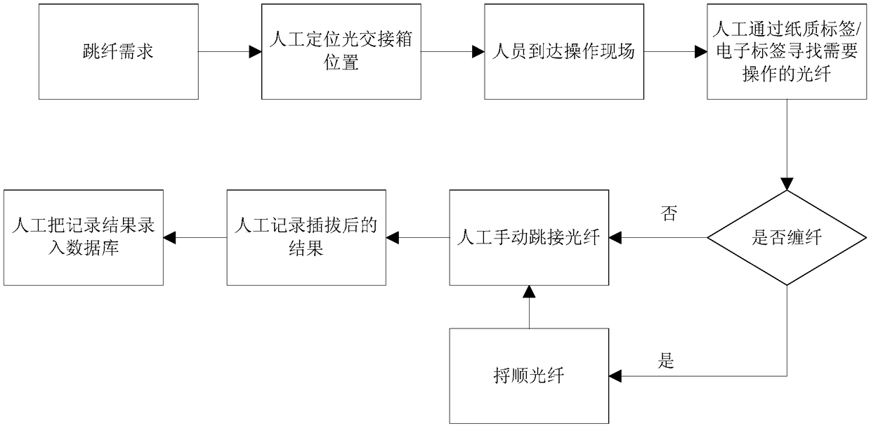
specific as figure 1 As shown, in the existing ODF or optical delivery box technical solutions, it is necessary to manually find the position of the ODF or optical delivery box, and then manually identify the optical fiber number through the paper label or electronic label on the optical fiber, and then manually observe the ODF or optical delivery box. For the winding situation of the optical fiber, if the optical fiber that needs to be spliced ​​is seriously entangled, it is necessary to manually smooth the optical fiber without affecting the rest of the existing business, then manually jump the optical fiber, manually record the result of the optical fiber jump, and then manually enter the recorded data into Database, if the optical fiber is seriously entangled during jumping and it is impossible to identify which fibers have services and which fibers have no services, maintenance is very difficult, resulting in a huge waste of existing fiber resources

Method used


Image

  • Optical fiber automatic jump connection device
  • Optical fiber automatic jump connection device
  • Optical fiber automatic jump connection device

Examples


Embodiment Construction

[0047] The technical solutions in the embodiments of the present invention will be clearly and completely described below in conjunction with the accompanying drawings in the embodiments of the present invention. Obviously, the described embodiments are only some of the embodiments of the present invention, not all of them. Based on the embodiments of the present invention, all other embodiments obtained by persons of ordinary skill in the art without making creative efforts belong to the protection scope of the present invention.

[0048] It should also be noted that the "up", "down", "left", "right", "front, and back" mentioned in this article to describe the orientation do not refer to this orientation unless otherwise specified, and are just for the convenience of description The product is placed in different directions, and its description is also different. Orientations that can be understood by those of ordinary skill in the art without creative work all belong to the p...


PUM


Abstract

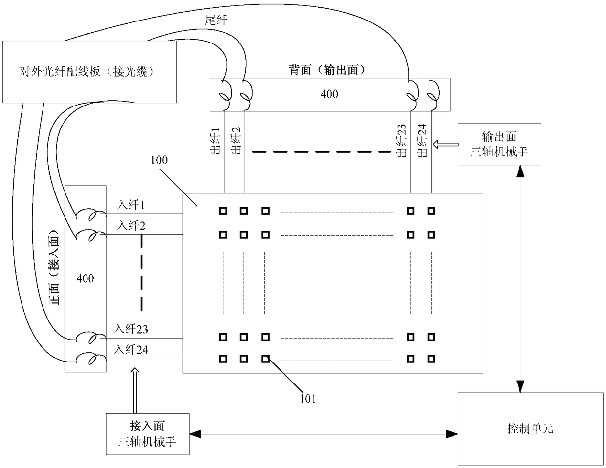
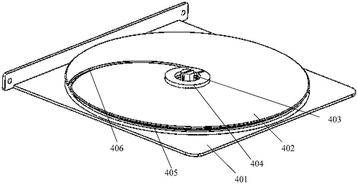
The invention discloses an optical fiber automatic jump connection device. The device is used for realizing automatic optical fiber jump connection of N access optical fibers and N output optical fibers, and comprises an optical fiber matching symmetrical matrix disk (100), two sets of optical fiber receiving disk groups (400) and two sets of triaxial mechanical arms and a control unit; the two sets of triaxial mechanism arms are respectively arranged at an access face and an output face of the optical fiber matching symmetrical matrix disk (100); according to operation command information, the control unit controls actions of the triaxial mechanism arms; the access optical fiber and the output optical fiber of the command in the operation commands are plugged out from an optical fiber butt joint (101) of an initial position and moved to and inserted into the optical fiber butt joint (101) of a target position, thus, optical fiber jump connection is realized. The optical fiber automatic jump connection device can realize remote control, intelligent plugging in and plugging out of the optical fibers, automatic recording for plugging in and plugging out operations, automatic settlingand storage for the optical fibers, automatic recording for results and data uploading, and is highly reliable, thus, maintenance cost is reduced, and maintenance timeliness is excellent.

Description

technical field [0001] The invention relates to the sub-technical field of communication equipment, in particular to an optical fiber automatic jumper device for optical fiber connection. Background technique [0002] With the development of communication technology, optical fiber communication has become the mainstream of communication physical channels. In optical fiber transmission lines, an optical cable usually includes multiple optical fibers, which are realized in the optical distribution frame (ODF) or optical cable junction box (optical junction box). Corresponding connection with another optical cable or multiple optical fibers of the end user, the optical fiber physical channel in the ODF or the optical transmission box will be rewired according to the connection needs in the application, that is, re-plugging and docking, and there are often maintenance problems operate. [0003] The work of traditional ODF or optical cross-box plugging and docking, fiber jumping...

Claims


Application Information

Patent Timeline
IPC IPC(8): G02B6/38G02B6/40
CPCG02B6/3833G02B6/3897G02B6/40
Inventor 刘宏吴沙张卫东徐美发
Owner 北京瑞祺皓迪技术股份有限公司
Learn More