A method for quickly modeling the suspension force of a rotor of a bearingless flux-switched motor

A technology of magnetic flux switching motor and modeling method, which is applied in electrical digital data processing, special data processing applications, instruments, etc., can solve the problem of sensitive motor structure parameters, inability to obtain the analytical expression of air gap magnetic density, complex model structure, etc. question

Inactive Publication Date: 2018-12-18
FUZHOU UNIV
View PDF0 Cites 1 Cited by
  • Summary
  • Abstract
  • Description
  • Claims
  • Application Information

AI Technical Summary

Problems solved by technology

However, most of the current BFSPMM related theoretical analysis, levitation force and electromagnetic torque model construction still rely on finite element analysis and equivalent magnetic network, which has defects such as long calculation time and complex model structure.
Similarly, since the analytical expression of the air gap flux density cannot be obtained, the finite element analysis and the equivalent magnetic network method are very sensitive to the structural parameters of the motor, and slight changes in the motor structure will bring a lot of model reconstruction work and calculation time. Relevant mathematical models are not practically universal

Method used


Image

  • A method for quickly modeling the suspension force of a rotor of a bearingless flux-switched motor
  • A method for quickly modeling the suspension force of a rotor of a bearingless flux-switched motor
  • A method for quickly modeling the suspension force of a rotor of a bearingless flux-switched motor

Examples


Embodiment

[0199] 1. Used for air gap permeance calculation

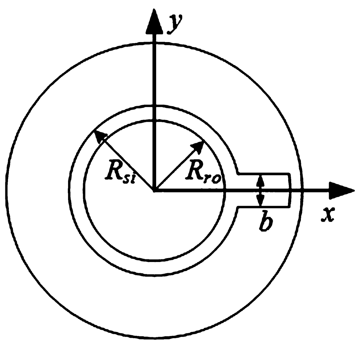
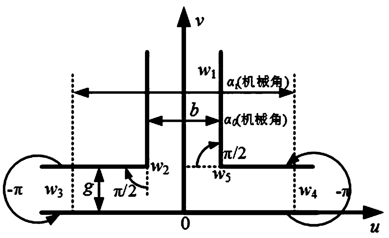
[0200] When the surface of the rotor is smooth and the stator has teeth and slots, the air gap permeability Λ s (θ r ) calculation as an example. After the stator teeth and slots (Fig. 2(a)) are expanded (Fig. 2(b)), the permeance distribution of the single salient pole air gap under a single slot can be expressed as:

[0201]

[0202] alpha 0 with alpha t Respectively represent the slot width and tooth pitch mechanical angle.

[0203]

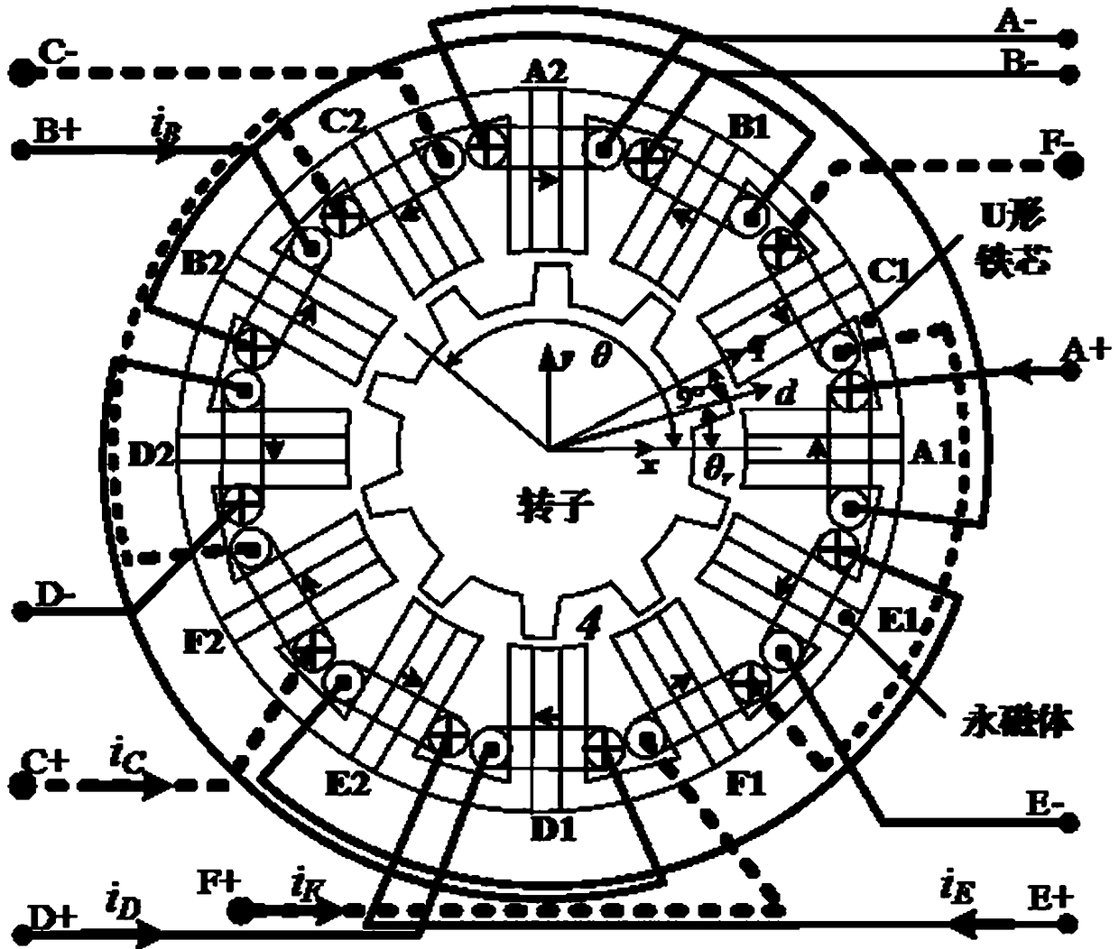
[0204] The motor of the present invention has a 12 / 10 structure, the permanent magnet is equivalent to an air gap, the U-shaped iron core of the motor stator has 24 teeth, and the rotor has 10 teeth. Therefore, it can be seen from formula (1) that when only the stator salient pole effect is considered, the Fourier series expansion of the air gap flux density distribution is:

[0205]

[0206] where b s with τ s are stator slot width and tooth pitch respectively, β s is the va...


PUM


Abstract

A method for quickly modeling the suspension force of a rotor of a bearingless flux-switched motor is provided. The method comprises the steps of calculating the air-gap permeance Lamdas (theta) whenthe rotor is smooth, and the air-gap permeance Lamdas (theta, theta r) when the stator is smooth, and calculating the air-gap permeance Lambda sr (theta1 theta r) according to the air gap length g, Lamdas (theta), and Lambda sr (theta1 theta r); obtaining the magnetomotive force of the permanent magnet and the phase current at the air gap by using the stator and rotor Carter coefficients. Magneticdensity generated by permanent magnet and phase current at air gap is calculated by air gap magnetomotive force and air gap permeability respectively. The sum of the air gap flux densities generatedby the power part of the permanent magnet and the phase current is calculated as the bias magnetic field in the levitation force calculation, and the air gap flux densities generated by the levitationpart of the phase current are calculated as the air gap modulated flux densities. A levitation force receive by that rotor is calculated by the air gap modulate magnetic density and the air gap biased magnetic density, and the modeling process of the levitation force of the rotor is complete.

Description

technical field [0001] The invention relates to the technical field of motors, in particular to a fast modeling method for rotor suspension force of a bearingless magnetic flux switching motor. Background technique [0002] Compared with the traditional rotor permanent magnet permanent magnet synchronous motor, the stator permanent magnet flux switching motor (Flux-Switching Permanent Magnet Machines, FSPMM) is placed on the stator side, and the rotor is simply laminated by silicon steel sheets. It has the advantages of simple and reliable structure, easy heat dissipation and high torque density. Therefore, applying the bearingless technology to the traditional FSPMM, that is, Bearingless Flux-Switch Permanent MagnetMachines (BFSPMM), without mechanical bearings brought by the bearingless technology, has no need for lubrication, between the stator and the rotor Under the premise of the advantages of complete isolation and other advantages, it overcomes the shortcomings of t...

Claims


Application Information

Patent Timeline
IPC IPC(8): G06F17/50
CPCG06F30/23
Inventor 周扬忠郑梦飞钟天云
Owner FUZHOU UNIV
Why Eureka
Try Eureka