A mobile energy storage battery cabinet with excellent heat dissipation

A mobile energy storage and battery cabinet technology, which is applied in the direction of secondary batteries, battery components, circuits, etc., can solve the problems of low manual handling efficiency, increased handling costs, and heavy battery cabinets, so as to reduce labor output and save The effect of high cost and heat dissipation efficiency

Inactive Publication Date: 2018-12-18
山东天瀚新能源科技有限公司
View PDF0 Cites 4 Cited by
  • Summary
  • Abstract
  • Description
  • Claims
  • Application Information

AI Technical Summary

Problems solved by technology

[0003] As the protective shell of the battery, the battery cabinet must have a heat dissipation function. The existing battery cabinets have some cooling holes on the surface for heat dissipation, which can only meet the heat dissipation requirements of a single or a small number of batteries. For multiple batteries

Method used


Image

  • A mobile energy storage battery cabinet with excellent heat dissipation
  • A mobile energy storage battery cabinet with excellent heat dissipation
  • A mobile energy storage battery cabinet with excellent heat dissipation

Examples


Embodiment 1

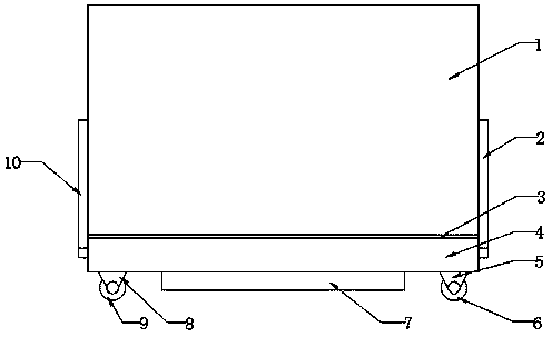
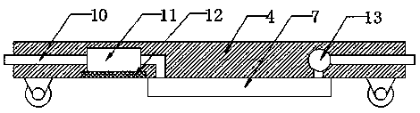
[0031] see Figure 1-4 , this embodiment provides a mobile energy storage battery cabinet with excellent heat dissipation, including a cabinet 1, a base 4 and a liquid storage tank 7; the cabinet 1 is arranged above the base 4, and the connection between the cabinet 1 and the base 4 A heat insulation board 3 is arranged at the place to avoid heat transfer between the cabinet body 1 and the base 4; the liquid storage tank 7 is fixed to the lower part of the base 4 to provide the cooling liquid required by the cabinet body 1; the cabinet body 1 The right side of the base 4 communicates with each other through the liquid inlet pipe 2, and the left side communicates with each other through the liquid outlet pipe 10; A cooling box 11 is installed on the pipe section of the pipe 10 inside the base 4; the lower part of the cooling box 11 is fixedly connected to a heat-conducting aluminum mesh 12, and the inside of the cooling box 11 is filled with a refrigerant for cooling the coolin...

Embodiment 2

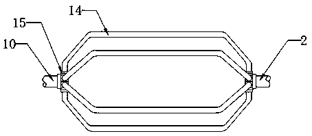
[0036] see Figure 5-8 , a mobile energy storage battery cabinet with excellent heat dissipation, further comprising a pipeline fixing device 18 fixed on the inner wall of the cabinet body 1 and corresponding in number to the cooling pipeline 4; the pipeline fixing device 18 includes a 7-shaped hook plate 19 and 7-shaped hook plate 21; the 7-shaped hook plate 19 and 7-shaped hook plate 21 relative settings, 7-shaped hook plate 19 and 7-shaped hook plate 21 is surrounded by a pipeline fixing groove, the right side of the pipeline fixing groove is provided with a trapezoidal notch 20, and the notch faces outward, and the cooling pipeline 14 is pressed into the pipeline fixing groove from the trapezoidal notch 20, so that the cooling pipeline 14 Embedded in the pipeline fixing groove, so as to complete the fixing of the cooling pipeline 14, and also facilitate the disassembly of the cooling pipeline 14; the 7-shaped hook plate 19 and 7-shaped hook plate The material ...


PUM


Abstract

The invention provides a mobile energy storage battery cabinet with excellent heat dissipation, belonging to the technical field of the battery cabinet, comprising a cabinet body, a base and a liquidstorage tank. The cabinet body is arranged above the base, and a heat insulating plate is arranged at the joint of the cabinet body and the base; The liquid storage tank is fixed with the lower part of the base; The cabinet body and the right side of the base are communicated with each other through a liquid inlet pipe, and the left side is communicated with each other through a liquid outlet pipe. The invention pumps the coolant inside the liquid storage tank into the cooling pipes inside the tank, and utilizes the aluminum cooling pipes to quickly absorb the heat inside the tank, and transfers the heat to the coolant flowing through the cooling pipes, so as to realize the rapid cooling of the tank and high heat dissipation efficiency. Through the cooperation of the universal wheel and the directional wheel, not only the accuracy of the cabinet body in the moving process, but also the stability of the cabinet body when the cabinet body is stationary is ensured, which not only saves the cost and reduces the labor output, but also has the practical and convenient characteristics.

Description

technical field [0001] The invention relates to a battery cabinet, in particular to a mobile energy storage battery cabinet with excellent heat dissipation. Background technique [0002] With the advancement of society, the development of the battery industry is also changing with each passing day, and the application fields of batteries are becoming more and more extensive. Based on safety considerations, batteries need to be fully protected during application. [0003] As the protective shell of the battery, the battery cabinet must have a heat dissipation function. The existing battery cabinets have some cooling holes on the surface for heat dissipation, which can only meet the heat dissipation requirements of a single or a small number of batteries. For multiple batteries In addition, most of the existing battery cabinets are relatively heavy, and long-distance mobile transportation is carried out by manual handling or mechanical hoisting, and the efficiency of manual h...

Claims


Application Information

Patent Timeline
IPC IPC(8): H01M2/10H01M10/613H01M10/6567H01M50/20H01M50/256
CPCH01M10/613H01M10/6567H01M50/256H01M50/20Y02E60/10
Inventor 陈凡伟李雯
Owner 山东天瀚新能源科技有限公司
Why Eureka
Try Eureka