
A wireless common source wireless energy transmission method and system

A technology of wireless energy transmission and common source, applied in the direction of circuit devices, electrical components, etc., can solve the unsolved problems such as wireless synchronization of TR transmitting array elements, and achieve the effect of avoiding electromagnetic interference

Active Publication Date: 2019-06-28
深圳市宇能无线技术有限公司
View PDF2 Cites 0 Cited by
  • Summary
  • Abstract
  • Description
  • Claims
  • Application Information

AI Technical Summary

Problems solved by technology

However, multiple TR transmitting elements in this patent still need to share the same frequency source through a wired electrical connection, which does not solve the problem of wireless synchronization between multiple spatially separated TR transmitting elements

Method used


Image

  • A wireless common source wireless energy transmission method and system
  • A wireless common source wireless energy transmission method and system
  • A wireless common source wireless energy transmission method and system

Examples


example 1

[0107] Example 1: Frequency-separated wireless energy transmission based on wireless common source

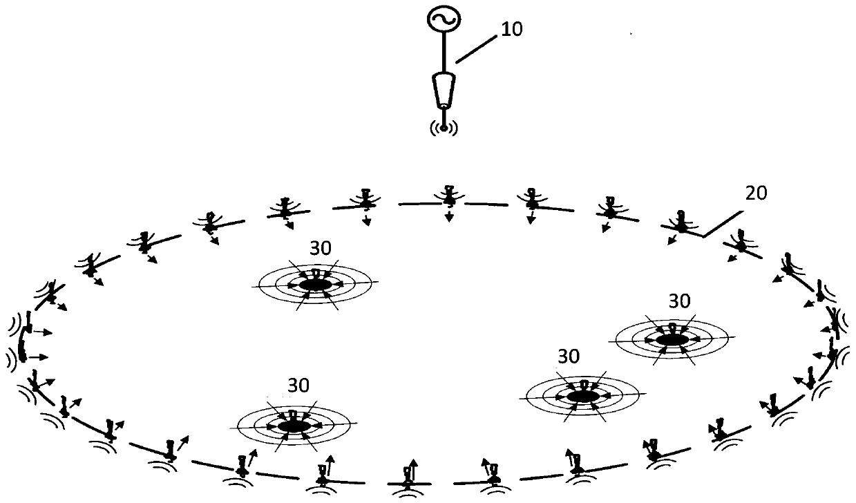
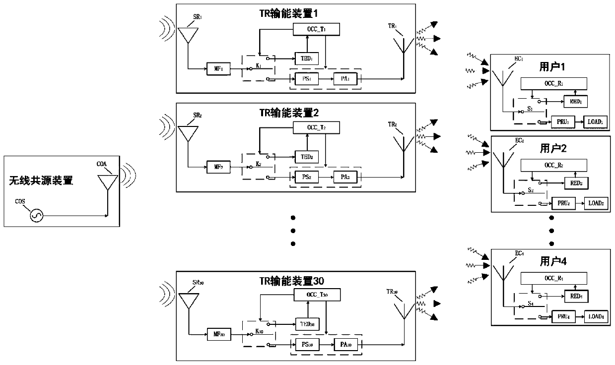
[0108] The structural block diagram of this example is as follows image 3 As shown, there is one wireless common source device, 30 TR energy transmitting devices (TR energy transmitting devices 1-30) and 4 users (users 1-4), and the users here can be understood as energy receiving devices. The wireless common source device includes at least one single-frequency signal source with a frequency of 1.225GHz, and one transmitting antenna with a center frequency of 1.225GHz. Each TR energy transmission device includes at least 1 frequency multiplier, 1 detector, 1 amplifier, 1 phase shifter, 1 receiving antenna with a center frequency of 1.225GHz, and 1 transmit antenna with a center frequency of 2.45GHz ; Each user includes at least one 2.45GHz receiving antenna, one detector, one rectifier and one load.

[0109] The structural block diagram of the wireless common source device i...

example 2

[0137] Example 2: Polarization-separated wireless energy transmission based on wireless common source

[0138] The structural block diagram of this example is as follows Figure 5As shown, there is one wireless common source device, 30 TR energy transmitting devices (TR energy transmitting devices 1-30) and 4 users (users 1-4), and the users here can be understood as energy receiving devices. The wireless common source device includes at least one single-frequency signal source with a frequency of 2.45GHz, and one vertically polarized transmitting antenna with a center frequency of 2.45GHz; each TR energy transmission device includes at least one detector, one amplifier, 1 phase shifter, 1 vertically polarized receiving antenna with a center frequency of 2.45GHz, and 1 horizontally polarized transmit antenna with a center frequency of 2.45GHz; each user includes at least one 2.45GHz horizontally polarized receive antenna, 1 detector, 1 rectifier and 1 load.

[0139] The stru...


PUM


Abstract

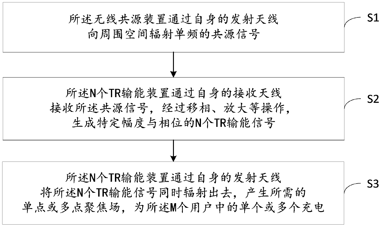
The invention discloses a wireless common-source wireless energy transmission method and system. The system consists of a wireless common source device, N TR energy transmission devices, and M users,wherein M and N are positive integers. The method comprises the following steps: the wireless common-source device radiates a single-frequency common-source signal to the surrounding space through a transmitting antenna of the wireless common-source device; The N TR energy transmission devices receive the common source signals through their own receiving antennas, and generate N TR energy transmission signals with specific amplitudes and phases through phase shifting and amplification operations. The N TR energy transmission devices simultaneously radiate the N TR energy transmission signals through their own transmitting antennas to generate a required single-point or multi-point focusing field to charge one or more of the M subscribers. The N TR energy transmission devices simultaneouslyradiate the N TR energy transmission signals through their own transmitting antennas to generate a single-point or multi-point focusing field to charge one or more of the M subscribers. The N TR energy transmission devices have no source, share the same radio source, and can maintain stable phase difference between each other. Therefore, the technical scheme of the invention can be used for solving the wireless synchronization problem between a plurality of spatially separated time inversion TR transmitting array elements.

Description

technical field [0001] The invention relates to the technical field of wireless energy transmission, in particular to a wireless common source wireless energy transmission method and system. Background technique [0002] Time Reversal (TR, Time Reversal) is a new type of acoustic wave transmission and control technology developed at the end of the 20th century. It was introduced into the field of electromagnetics by M. Fink and his research group members in 2004. The central idea of ​​TR is to propagate sound or electromagnetic waves back to the original source in a complex environment. Theoretical and experimental studies have shown that TR electromagnetic waves can simultaneously form a point focus at one or more designated target positions. Under certain conditions, they can also It exhibits sub-wavelength focusing characteristics beyond the Rayleigh diffraction limit and produces high-precision non-diffraction electromagnetic beams. These unique physical properties allo...

Claims


Application Information

Patent Timeline
Patent Type & Authority Patents(China)
IPC IPC(8): H02J50/20H02J50/40H02J50/80
CPCH02J50/20H02J50/40H02J50/80
Inventor 赵德双李涛徐新松
Owner 深圳市宇能无线技术有限公司
Learn More