
Design method of broadband high-power circular polarizer

A technology of circular polarizer and design method, which is applied to antennas, electrical components, etc., can solve the problems of low power capacity, narrow bandwidth, and bulky devices, and achieve the effect of high power capacity characteristics

Active Publication Date: 2021-12-24
UNIV OF ELECTRONICS SCI & TECH OF CHINA
View PDF5 Cites 0 Cited by
  • Summary
  • Abstract
  • Description
  • Claims
  • Application Information

AI Technical Summary

Problems solved by technology

[0005] Aiming at the problems of low power capacity, narrow bandwidth, and bulky device of the waveguide circular polarizer in the prior art, the present invention proposes a broadband high-power circular polarizer used in a high-power gyroscopic TWT link system design method

Method used


Image

  • Design method of broadband high-power circular polarizer
  • Design method of broadband high-power circular polarizer
  • Design method of broadband high-power circular polarizer

Examples


Embodiment Construction

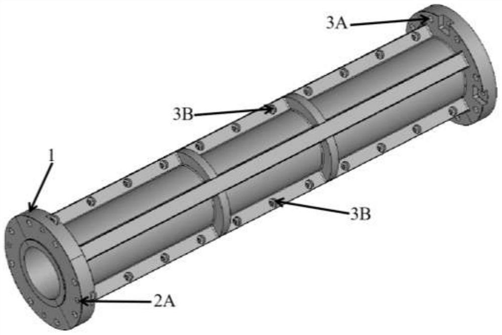
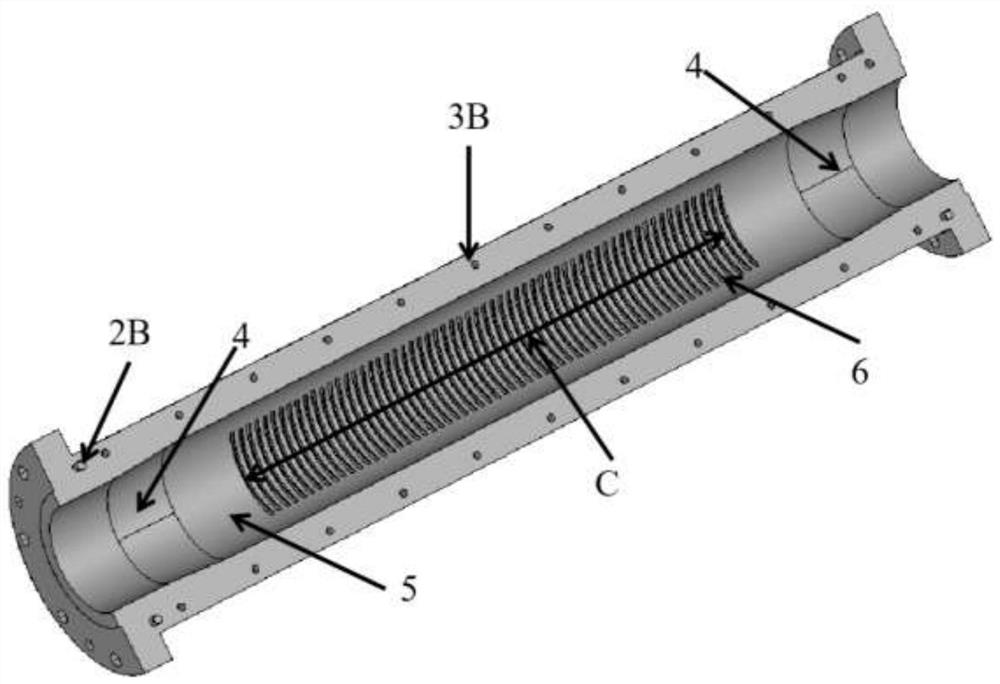
[0031] The present invention will be further described in detail below in conjunction with the accompanying drawings to design a circular polarizer for high-power millimeter-wave systems operating at 16GHz-23GHz.

[0032] S1. According to the known calibers of the front and rear cascaded devices, determine the radius of the input port and the output port of the circular polarizer to be 16 mm.

[0033] S2. Determine the maximum phase shift error of the circular polarizer within the working bandwidth and the initial length L of the phase shift section of the waveguide according to the design objective, and design the initial model of the phase shift section of the waveguide.

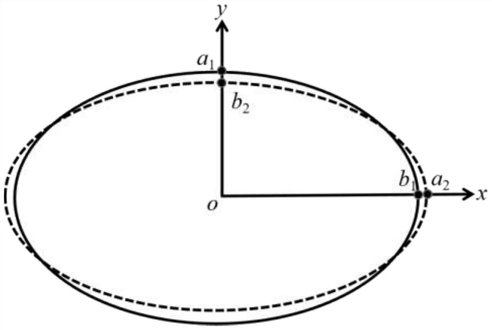
[0034] S2-1. The working frequency band of the designed circular polarizer is 16GHz-23GHz, and its working frequency band is divided into 2 small working frequency bands, respectively 20-23GHz (frequency band A) and 16-20GHz (frequency band B); select an ellipse As the first phase-shifting section, the wav...


PUM


Abstract

The invention discloses a design method of a broadband high-power circular polarizer, which belongs to the field of high-power millimeter wave devices. According to the method, an equivalent low-dispersion waveguide phase shift section is obtained by using the combination of over-mode waveguide structures with various dispersion characteristics, so that the phase constant difference of two orthogonal linear polarization modes after entering the waveguide phase shift section tends to be a constant, and a stable phase difference can be obtained after a wave beam passes through the waveguide phase shift section. Meanwhile, the over-mode waveguide is used as a phase shift carrier, no medium insertion piece or other objects prone to breakdown exist, and the high-power capacity characteristic is achieved.

Description

technical field [0001] The invention relates to the field of high-power millimeter-wave devices, in particular to a design method for a broadband high-power waveguide circular polarizer for high-power millimeter-wave transmission links. [0002] technical background [0003] Circular polarizer is a widely used device in microwave system, mainly used for mutual conversion between linear and circular polarization. Generally, the waveguide circular polarizer can decompose the incident linearly polarized electromagnetic wave into two equal-amplitude and mutually orthogonal linearly polarized waves, and then adjust the phase difference of the two linearly polarized waves to reach 90° , and then synthesized into a beam of circularly polarized waves; or decompose the circularly polarized wave into two equal-amplitude orthogonal linearly polarized waves with a phase difference of 90°, adjust the phase to make them in phase, and then synthesize a beam of linearly polarized waves Wave...

Claims


Application Information

Patent Timeline
Patent Type & Authority Applications(China)
IPC IPC(8): H01Q15/24
CPCH01Q15/24
Inventor 吴泽威张冉袁浩俊王敏行黄帅蒲友雷王建勋罗勇
Owner UNIV OF ELECTRONICS SCI & TECH OF CHINA
Learn More