

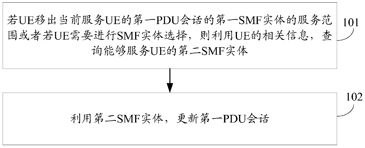
A method of inserting smf and amf entities
An entity and service scope technology, applied in the field of communication, can solve problems such as inability to effectively insert intermediate SMF
- Summary
- Abstract
- Description
- Claims
- Application Information
AI Technical Summary
Problems solved by technology
Method used
Image

Examples
example 1
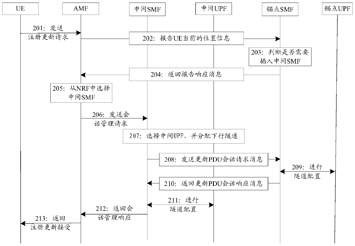
[0153] Please refer to figure 2 , represents a flow chart of the process of inserting an SMF entity in the first embodiment of the present invention. In Example 1, the anchor SMF entity determines that an intermediate SMF entity needs to be selected and indicates the AMF entity, and the UE triggers the process of inserting an SMF entity. During the establishment of the PDU session, the anchor SMF entity subscribes the location information of the UE to the AMF entity. The process of inserting an SMF entity in instance 1 includes the following steps:
[0154] Step 201: When the UE moves out of the currently allocated registration area, it sends a registration update request message to the AMF entity through the new access network RAN base station;
[0155] Step 202: The AMF entity reports the current location information of the UE to the anchor SMF entity of each PDU session according to the PDU session information established by the UE; where the current location informati...
example 2
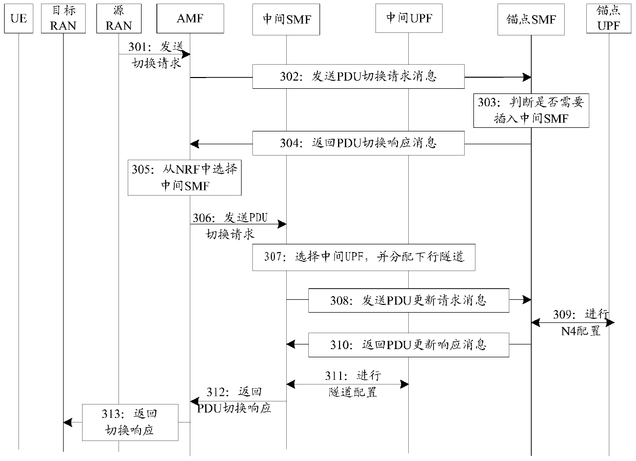
[0168] Please refer to image 3 , represents a flowchart of the process of inserting an SMF entity in the second embodiment of the present invention. In the second example, the anchor SMF entity determines that an intermediate SMF entity needs to be selected and instructs the AMF entity, and inserts the intermediate SMF after receiving the handover request message. The process of inserting an SMF entity in instance 2 includes the following steps:
[0169] Step 301: During the RAN handover process, the source base station sends a handover request message to the AMF entity;
[0170] Step 302: After receiving the handover request message, the AMF entity sends a PDU handover request message to the anchor SMF entity of each PDU session according to the PDU session information established by the UE; wherein, the PDU handover request message carries the current location information of the UE, The current location information of the UE may be the TAI information where the UE is curr...
example 3
[0183] Please refer to Figure 4 , represents a flow chart of the process of inserting an SMF entity in Example 3 of the present invention. In Example 3, the source NGRAN and the target NG RAN are switched based on the Xn interface, and the anchor SMF entity determines that an intermediate SMF entity needs to be selected and indicates the AMF entity, and inserts the intermediate SMF after receiving the N2 path switching request message. The process of inserting an SMF entity in Example 3 includes the following steps:
[0184]Step 401: During the handover process based on the Xn interface, the target base station sends an N2 path handover request message to the AMF entity;
[0185] Step 402: After receiving the N2 path switching request message, the AMF entity sends a message of the N11 interface to the anchor SMF entity of each PDU session according to the PDU session information established by the UE, which can carry the current location information of the UE, and the curren...
PUM
 Abstract
Description
Claims
Application Information