Pediatric blood shaking device
A blood and pediatric technology, applied in the field of medical devices, can solve the problems of low work efficiency, unstable test results, uneven mixing of blood and anticoagulant, etc., and achieve the effects of reducing work efficiency, novel structure, and simple and convenient operation.
- Summary
- Abstract
- Description
- Claims
- Application Information
AI Technical Summary
Problems solved by technology
Method used
Image

Examples
Embodiment 1
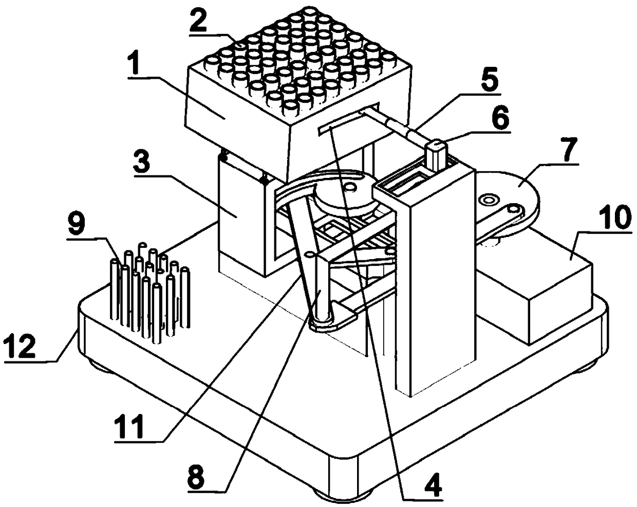
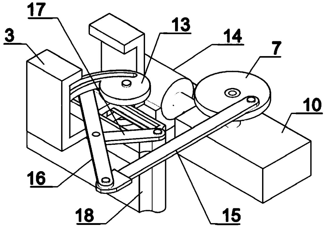
[0028] Embodiment one, by figure 1 , figure 2 , Figure 4 , Image 6 with Figure 9 Given, the present invention comprises base 18, and base 18 is fixed on base 12, and base 18 is provided with the first slide block 21 that can slide left and right, and the upper end of first slide block 21 is provided with pin bar 22, pin bar 22 is a common hinge, and will not be described too much here, the pin rod 22 is hinged with a crank linkage 11, the crank linkage 11 is equivalent to the transmission connection device of the present invention, and the upper end of the crank linkage 11 is provided with Grooved cam 13, grooved cam 13 is to offer an arc-shaped notch on the conventional cam, in order to drive the rotation of grooved cam 13, pin rod 22 upper ends can slide through the arc-shaped groove hole of grooved cam 13, when pin rod 22 When the first slider 21 slides left and right, the pin rod 22 drives the rotation of the grooved cam 13 by squeezing the inner wall of the notch ...
Embodiment 2
[0030] Embodiment two, on the basis of embodiment one, by figure 1 , figure 2 with Figure 4 Given, in order to realize the left and right sliding of the test tube rack 1, the crank linkage mechanism 11 includes a crank wheel 7, a first connecting rod 15, a second connecting rod 16 and a third connecting rod 17, and the crank wheel 7 is connected to the first connecting rod. The rod 15 is hinged, the front end of the first connecting rod 15 is hinged with the second connecting rod 16, the other end of the second connecting rod 16 is hinged with the pin rod 22 on the first slider 21, and the middle part of the second connecting rod 16 is connected with the third connecting rod. The connecting rod 17 is hinged, and the other end of the third connecting rod 17 is hinged on the base 18 with a pin rod 22;
[0031] In order to enable the hinge point on the second connecting rod 16 and the first slider 21 to move linearly left and right, the hinge point between the first connectin...
Embodiment 3
[0032] Embodiment three, on the basis of embodiment two, by figure 1 with Figure 9 Given, in order to realize that the second slider 6 slides back and forth, the upper end of the hinge joint between the first connecting rod 15 and the second connecting rod 16 is provided with a fourth connecting rod 8, and the upper end of the fourth connecting rod 8 is connected to the second sliding block. 6 fixed connection, the hinge of the first connecting rod 15 and the second connecting rod 16 is fixedly connected with the lower end of the fourth connecting rod 8, when the crank wheel 7 rotates, it drives the fourth connecting rod 8 to move back and forth, the fourth connecting rod 8 Drive the second slider 6 to slide back and forth on the second support frame.
PUM
 Abstract
Description
Claims
Application Information
 - Generate Ideas
- Intellectual Property
- Life Sciences
- Materials
- Tech Scout
- Unparalleled Data Quality
- Higher Quality Content
- 60% Fewer Hallucinations
Browse by: Latest US Patents, China's latest patents, Technical Efficacy Thesaurus, Application Domain, Technology Topic, Popular Technical Reports.
© 2025 PatSnap. All rights reserved.Legal|Privacy policy|Modern Slavery Act Transparency Statement|Sitemap|About US| Contact US: help@patsnap.com