Multistage chemical material screening and treatment device

A processing device and technology for chemical raw materials, applied in the field of multi-stage chemical raw material screening and processing devices, can solve problems such as low screening degree, reduced production efficiency, and raw material mixing, so as to improve screening efficiency, improve screening efficiency, and avoid bonding effect

Inactive Publication Date: 2018-12-21
福州市长乐区巧通工业设计有限公司
View PDF0 Cites 13 Cited by
  • Summary
  • Abstract
  • Description
  • Claims
  • Application Information

AI Technical Summary

Problems solved by technology

[0003] In fine chemical industry, when screening chemical raw materials, the previous screening equipment mostly used manual screening or mechanical screen screening, but for the screening of some finer chemical raw materials, the previous screening devices could not To ensure the multi-level screening, the screening degree is low, it is easy to cause incomplete screening or the re-mixing of the screened raw materials, which not only affects the later processing and use, but also reduces the production efficiency, which is not conducive to efficient chemical processing

Method used


Image

  • Multistage chemical material screening and treatment device
  • Multistage chemical material screening and treatment device
  • Multistage chemical material screening and treatment device

Examples


Embodiment 1

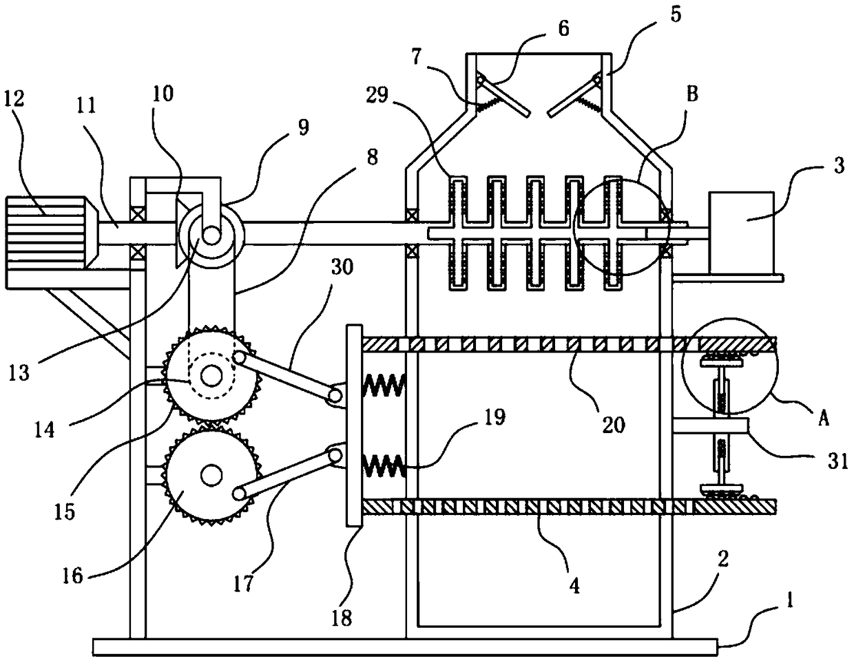
[0021] see Figure 1-3 , a multi-stage chemical raw material screening processing device, comprising a carrier frame 1, a screening bucket 2 is fixedly installed on the carrier frame 1, a feed pipe 5 is installed on the upper end of the screening bucket 2, and a feed pipe 5 is fixedly installed on the carrier frame 1 Drive motor 12, the output shaft of drive motor 12 is fixedly installed with drive shaft 11 coaxially. The provided drive motor 12 is used as the power source of the device for driving the drive shaft 11 to rotate.

[0022] The surface of the drive shaft 11 is sleeved and fixed with a driving bevel gear 10, the driving bevel gear 10 is meshed with a driven bevel gear 9, the driven bevel gear 9 is coaxially fixed with a driving pulley 13, and the side wall of the bearing frame 1 is rotatable. A driving gear 15 and a driven gear 16 meshingly connected are provided, and the driving gear 15 is coaxially fixed with a driven pulley 14 connected to the driving pulley 13...

Embodiment 2

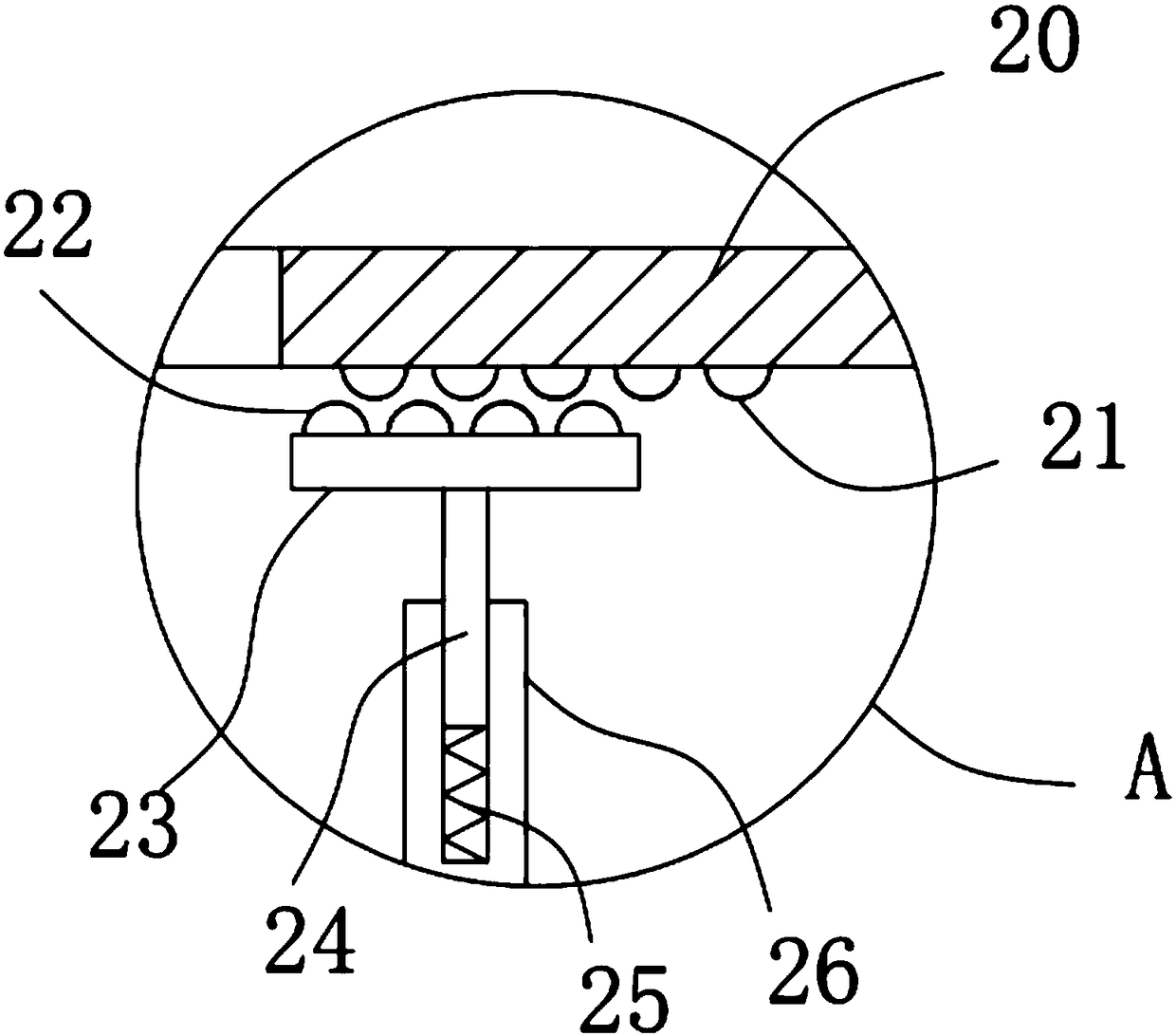
[0026] On the basis of Embodiment 1, in addition, an extension plate 31 is fixedly installed on the right side of the screening bucket 2, and the upper and lower side walls of the extension plate 31 are respectively vertically fixed with a sleeve 26, and the sleeve 26 is slidingly provided with a slide bar 24 and a The sliding bar 24 is fixedly connected to the longitudinal return spring 25, and the end of the sliding bar 24 away from the casing 26 is fixed with a horizontal plate 23, and the horizontal plate 23 is fixed with a bump II22. The bump I21 abutting against the bump II22 is fixed on the surface.

[0027] When the first sieve plate 20 and the second sieve plate 4 move laterally, the protrusion I21 provided on the first sieve plate 20 and the second sieve plate 4 and the protrusion II22 on the horizontal plate 23 produce a relative displacement, and the longitudinal return spring Under the action of the elasticity of 25, the sliding bar 24 drives the horizontal plate ...

Embodiment 3

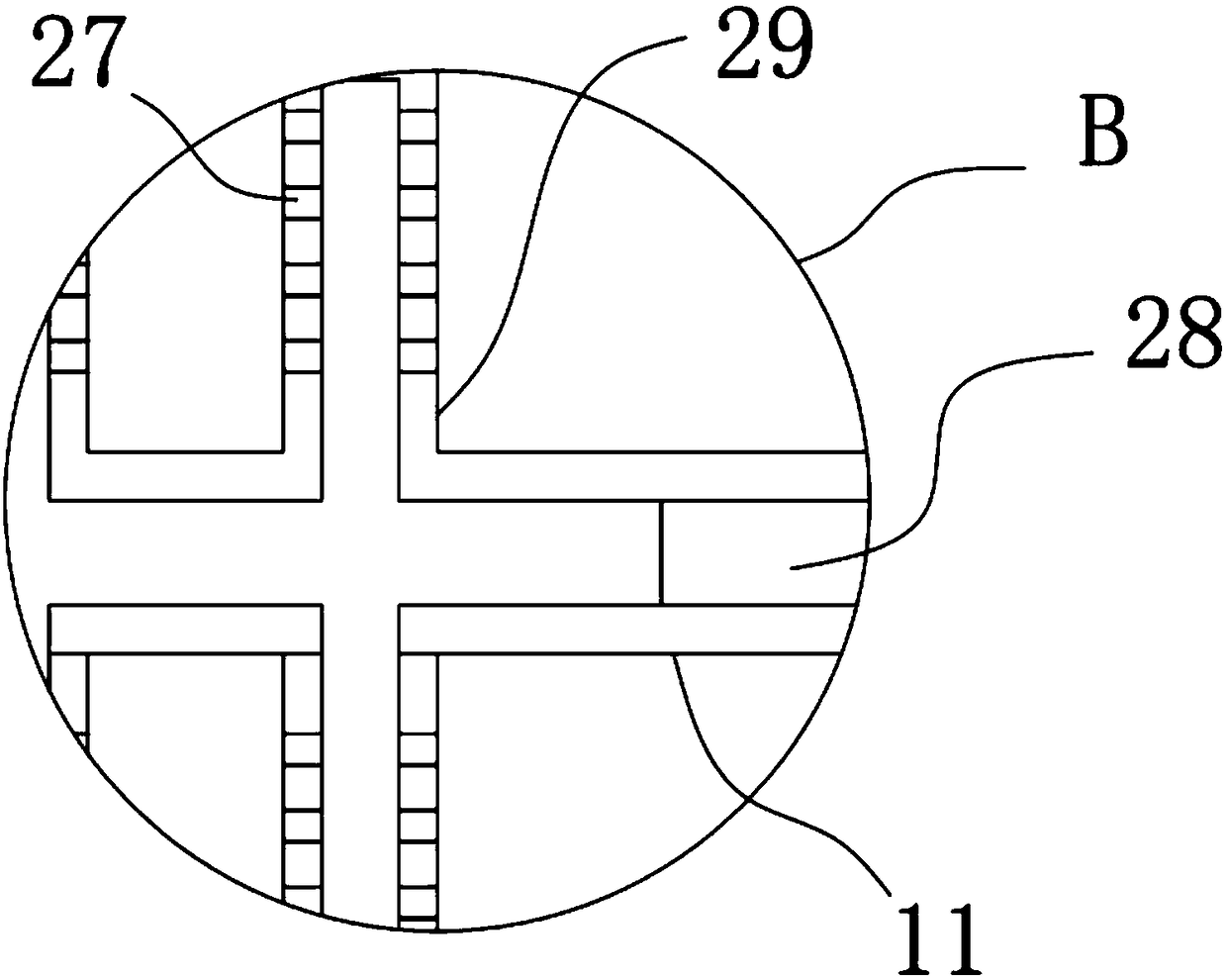
[0029] On the basis of embodiment 2, in addition, sieve barrel 2 right side walls are fixed with hot air blower 3, and the outlet end of hot air blower 3 is communicated with and installed with air intake pipe 28, and driving shaft 11 inside is provided with cavity, and air intake pipe 28 extends to Inside the cavity, the surface of the driving shaft 11 is evenly fixed with several rotating tubes 29 communicating with the cavity of the intake pipe 28, and the surface of the rotating tube 29 is evenly provided with several air outlet holes 27.

[0030] The hot air blower 3 injects the hot air generated into the cavity of the drive shaft 11 through the air inlet pipe 28, and the rotation of the drive shaft 11 drives the rotation of the rotating tube 29, and the rotating tube 29 pairs of materials that fall into the screening bucket 2 from the feed pipe 5 The chemical raw materials are broken up, which promotes the dispersion of the chemical raw materials. At the same time, the ho...


PUM


Abstract

The invention discloses a multistage chemical material screening and treatment device and relates to the technical field of chemical devices. The multistage chemical material screening and treatment device comprises a bearing frame, wherein a screening barrel is fixedly mounted on the bearing frame; feeding tubes are mounted at the upper end of the screening barrel; a driving motor is fixedly mounted on the bearing frame; a driving belt pulley is coaxially fixed on a driven bevel gear; and the left end of a pull rod II and the left end of a pull rod I are separately hinged on the front surfaceof a driving gear and the front surface of a driven gear in an eccentric manner. The multistage chemical material screening and treatment device separately pulls the pull rod II and the pull rod I byvirtue of the driving gear and the driven gear which are in meshing connection, thereby realizing the left and right reciprocating motion of a second screening plate and a first screening plate, andrealizing the second-stage screening of chemical materials. The relative displacement between protruding blocks I and protruding blocks II realizes the vibration of the second screening plate and thefirst screening plate so as to improve the screening efficiency. Rotating tubes can rotate to scatter the chemical materials, and the hot air sprayed from air outlets can dry the chemical materials toavoid the bonding of the chemical materials so as to ensure great improvement in subsequent screening efficiency.

Description

technical field [0001] The invention relates to the technical field of chemical devices, in particular to a multi-stage chemical raw material screening and processing device. Background technique [0002] Chemical industry, that is, the chemical industry, has spread to all aspects of human life. In modern life, chemical products are inseparable almost anytime and anywhere. From material life such as clothing, food, housing and transportation to spiritual life such as culture, art and entertainment, chemical products are required to serve them. Some chemical products play an epoch-making important role in the history of human development. Their production and application even represent a certain historical stage of human civilization. Anyone who uses chemical methods to change the composition or structure of substances, or to synthesize new substances belongs to chemical production technology, that is, chemical technology, and the resulting products are called chemicals or ...

Claims


Application Information

Patent Timeline
Patent Type & Authority Applications(China)
IPC IPC(8): B07B1/28B07B1/42B07B1/46B02C13/02F26B21/00
CPCB07B1/28B02C13/02B07B1/42B07B1/46B07B2201/04F26B21/00
Inventor 杨哲
Owner 福州市长乐区巧通工业设计有限公司
Why Eureka
Try Eureka