High-efficiency cleaning device for precise workpieces

A technology for cleaning equipment and workpieces, applied in the direction of cleaning methods using liquids, cleaning methods and utensils, chemical instruments and methods, etc., can solve the problems of poor cleaning quality, low cleaning efficiency, and small application range of precision workpieces, and achieve Improve cleaning efficiency and cleaning quality, improve cleaning quality and cleaning efficiency, and reduce labor intensity

Inactive Publication Date: 2018-12-21
WUHU DEJIA INTELLIGENT TECH CO LTD
View PDF1 Cites 0 Cited by
  • Summary
  • Abstract
  • Description
  • Claims
  • Application Information

AI Technical Summary

Problems solved by technology

[0003] The object of the present invention is to provide a cleaning device with reasonable structure design, high working efficiency and high precision workpiece cleaning quality for the problems of low cleaning efficiency, poor precision workpiece cleaning quality, small application range and inconvenient operation in the existing precision workpiece cleaning equipment. Good, easy to operate, high-efficiency cleaning equipment for precision workpieces with a wide range of applications

Method used


Image

  • High-efficiency cleaning device for precise workpieces
  • High-efficiency cleaning device for precise workpieces

Examples


Embodiment 1

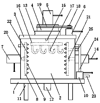
[0018] as attached figure 1 As shown, a high-efficiency cleaning equipment for precision workpieces includes a bottom plate 1, a cleaning chamber 2, a top cover 3, a rotating disk 4, cylinder one 5, a motor 6, cylinder two 7, a push plate 8, a water spray pipe 9 and a water delivery pump 10. It is characterized in that: the bottom plate 1 is set on the bracket 11, the cleaning chamber 2 is set on the bottom plate 1, and a drain pipe 12 is set on the cleaning room 2, and the top cover 3 is set on the cleaning chamber 2, and a fixed bearing 13 is arranged on the top cover 3, the rotating disk 4 is arranged in the fixed bearing 13, the cylinder one 5 is arranged on the rotating disk 4, and the cylinder one 5 is provided with Power cord 14, piston rod one 15, described motor 6 is arranged on cleaning chamber 1 top, and is provided with power cord 14, driving wheel 18 on motor 6, and described cylinder two 7 is arranged on cleaning chamber 1 side wall , and on cylinder two 7, be p...

Embodiment 2

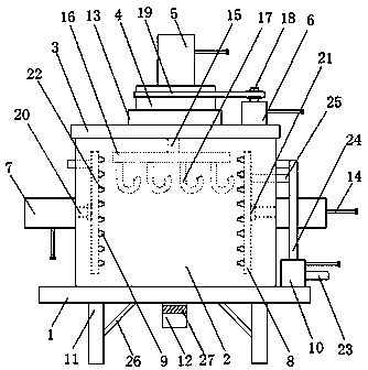
[0026] as attached figure 2 As shown, a high-efficiency cleaning equipment for precision workpieces includes a bottom plate 1, a cleaning chamber 2, a top cover 3, a rotating disk 4, cylinder one 5, a motor 6, cylinder two 7, a push plate 8, a water spray pipe 9 and a water delivery pump 10. It is characterized in that: the bottom plate 1 is set on the bracket 11, the cleaning chamber 2 is set on the bottom plate 1, and a drain pipe 12 is set on the cleaning room 2, and the top cover 3 is set on the cleaning chamber 2, and a fixed bearing 13 is arranged on the top cover 3, the rotating disk 4 is arranged in the fixed bearing 13, the cylinder one 5 is arranged on the rotating disk 4, and the cylinder one 5 is provided with Power cord 14, piston rod one 15, described motor 6 is arranged on cleaning chamber 1 top, and is provided with power cord 14, driving wheel 18 on motor 6, and described cylinder two 7 is arranged on cleaning chamber 1 side wall , and on cylinder two 7, be ...


PUM


Abstract

The invention discloses a high-efficiency cleaning device for precise workpieces. The device comprises comprises a bottom plate, a cleaning chamber, a top cover, a rotating disc, a first air cylinder,a motor, a second air cylinder, a push plate, a water spraying pipe and a water delivery pump, and is characterized in that the bottom plate is arranged on a support, the cleaning chamber is arrangedon the bottom plate, the top cover is arranged on the cleaning chamber, the rotating disc is arranged in a fixing bearing, the first air cylinder is arranged on the rotating disc, the motor is arranged at the top of the cleaning chamber, the second air cylinder is arranged on the side wall of the cleaning chamber, the push plate is arranged in the cleaning chamber, the water spraying pipe is arranged on the push plate, and the water delivery pump is arranged on the bottom plate. According to the device, precise workpieces needing to be cleaned are hung on a lifting hook of a connecting plateof a first piston rod, the first air cylinder and the first piston rod can drive the connecting plate to ascend or descend, so that the precision workpieces can ascend or descend, and the cleaning efficiency of the precise workpieces is improved.

Description

technical field [0001] The invention relates to a cleaning device, in particular to a high-efficiency cleaning device for precision workpieces. Background technique [0002] In the process of precision workpiece processing, stamping machines need to be used. The stamping machine needs to use lubricating oil in the process of stamping precision workpieces, so that the surface of precision workpieces after stamping is finished with lubricating oil. Therefore, after the precision workpiece stamping is completed, the enterprise Precision workpieces need to be cleaned. For example, the patent application number 201621135067.7 discloses a fully automatic CNC laser cleaning equipment, which solves the problem of low safety for operators, but it has the disadvantages of low cleaning efficiency, poor cleaning quality of precision workpieces, small scope of application, and difficult operation. The lack of inconvenience. Contents of the invention [0003] The object of the present...

Claims


Application Information

Patent Timeline
IPC IPC(8): B08B3/02B08B13/00
CPCB08B3/022B08B13/00
Inventor 汪保华严伟民
Owner WUHU DEJIA INTELLIGENT TECH CO LTD
Why Eureka
Try Eureka