Device and method for laser impact welding of metal foil plate based on intermediate layer automatic spraying

An automatic spraying and welding metal technology, which is applied in laser welding equipment, welding equipment, metal processing equipment, etc., can solve the problems of little improvement in laser shock welding of dissimilar difficult-to-weld metals, and the limitation of the upper plate size and spot size, so as to achieve the welding process Stable, efficient and highly automated results

Active Publication Date: 2018-12-21
JIANGSU UNIV
View PDF11 Cites 3 Cited by
  • Summary
  • Abstract
  • Description
  • Claims
  • Application Information

AI Technical Summary

Problems solved by technology

It overcomes the limitation that a certain flight distance must be given between the upper plate and the lower plate in the traditional laser shock welding method, and solves the problem that the size of the upper plate is limited by the size of the laser spot
However, it is still difficult to successfully weld metal materials that are difficult to weld
The patent with the publication number CN 103722291A introduces a laser shock welding device with continuously adjustable impact angle in a vacuum environment. Although the impact angle can be continuously adjusted to obtain welding states at different angles, it is difficult for laser shock welding of dissimilar difficult-to-weld metals The improvement is still small

Method used


Image

  • Device and method for laser impact welding of metal foil plate based on intermediate layer automatic spraying
  • Device and method for laser impact welding of metal foil plate based on intermediate layer automatic spraying
  • Device and method for laser impact welding of metal foil plate based on intermediate layer automatic spraying

Examples


Embodiment Construction

[0038] The present invention will be further described below in conjunction with the accompanying drawings and specific embodiments, but the protection scope of the present invention is not limited thereto.

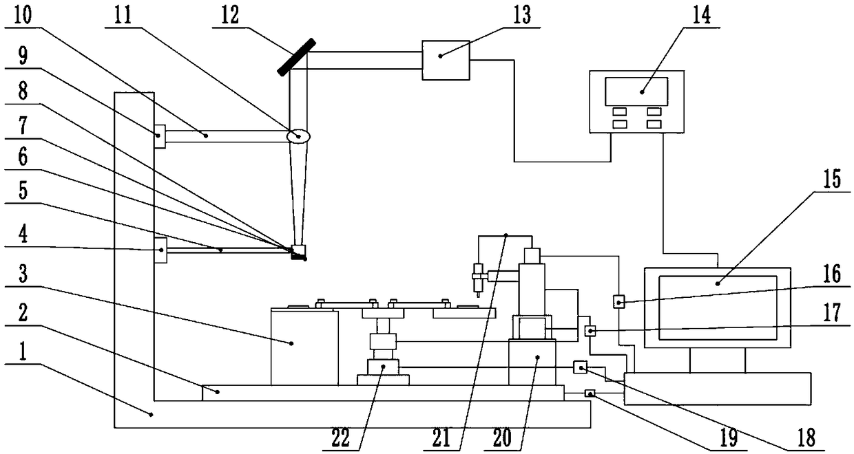
[0039] combined with figure 1 Shown is an embodiment of the device for laser shock welding of metal foil plates based on automatic spraying of the intermediate layer according to the present invention. The device includes a laser loading system, a control system, a placement conversion system, a welding system, and an automatic spraying of the intermediate layer. system and a three-dimensional mobile platform system; the middle layer spraying pen 37 in the middle layer automatic spraying system sprays the spraying liquid onto the substrate 23 on one side in the placement conversion system; the other side substrate 23 in the placement conversion system placed directly below the welding system; the laser beam emitted by the laser loading system is irradiated onto the constr...


PUM

PropertyMeasurementUnit
thicknessaaaaaaaaaa
thicknessaaaaaaaaaa

Abstract

The invention provides a device and method for laser impact welding of a metal foil plate based on an intermediate layer automatic spraying, relating to the field of laser impact pressure welding. Thedevice comprises a laser loading system, a control system, a placement conversion system, a welding system, an intermediate layer automatic spraying system, and a three-dimensional mobile platform system. The laser loading system comprises a focusing lens, a lens holder, a lens height adjuster, and a reflecting mirror. The control system comprises a computer, a strong pulse laser controller, a pneumatic controller, a stepper motor controller, an intermediate layer spraying controller, and a three-dimensional mobile platform controller. The placement conversion system comprises a placement platform and a conversion platform. The welding system comprises a constraining layer, an absorbing layer, and a welding processing base. The intermediate layer automatic spraying system comprises an intermediate layer spraying device. According to the device and method for laser impact welding of metal foil plate based on intermediate layer automatic spraying, the intermediate layer is sprayed ontothe surface of the substrate by adding the placement conversion system and the intermediate layer automatic spraying system. Then better welding quality is obtained by loading the laser to perform impact-welding on the coated substrate.

Description

technical field [0001] The invention belongs to the field of laser shock pressure welding in mechanical manufacturing, in particular to a device and method for laser shock welding of metal foil plates based on automatic spraying of an intermediate layer. Background technique [0002] In recent years, with the rapid development of modern industrial technology and the rapid development of science and technology, the miniaturization, precision and light weight of products have become one of the important trends in the development of the manufacturing industry. Therefore, the research on the related micro-device welding technology appear more and more important. However, the traditional metal foil connection technology has been unable to meet the development needs of new metal foil materials applied to micro parts. Solving the problem of connecting two layers of metal foil materials used in micro parts is of great significance to the improvement of the quality and cost reduction...

Claims


Application Information

Patent Timeline
Patent Type & Authority Applications(China)
IPC IPC(8): B23K20/06B23K20/08B23K20/26B23K20/24B23K26/00
CPCB23K20/06B23K20/08B23K20/24B23K20/26B23K26/00
Inventor 王霄邵蒙靳浩唐恒刘会霞
Owner JIANGSU UNIV
Why Eureka
Try Eureka