Line-driven robotic fish

A robotic fish and wire-driven technology, applied in the field of bionic robots, can solve the problems of difficult assembly, inconvenient research and application, and increased fish body mass, and achieve the effect of reducing overall weight and simple joint structure

Pending Publication Date: 2018-12-21
CHONGQING THREE GORGES UNIV
View PDF3 Cites 12 Cited by
  • Summary
  • Abstract
  • Description
  • Claims
  • Application Information

AI Technical Summary

Problems solved by technology

Patent CN101322878A proposes a toy robot fish with a fixed skeleton inside, a propeller to adjust the ups and downs, and an overall fish skin. A robotic fish supported by a skeleton and swinging by a single joint has been developed. The skeleton structure of the robotic fish is poorly streamlined and is only suitable for water surfaces; patent CN107380386A discloses a three-joint swing robotic fish, including three main drive joints, each of which is The driving joints each include a steering gear and a driving rod. The three joints are interlocked and sequentially driven to realize the swing of the fish tail. The fish joint structure of this robot is complicated. The use of the steering gear increases the mass of the fish body, which makes assembly difficult and the effect of sinking and floating unstable
[0004] Most of the existing robotic fish adopt an integrated structure, three-joint swing drive, and a skeleton support skin mode. The driving part takes up a lot of space, which is not conducive to the installation of other functional modules, and it is inconvenient for later research and application.

Method used


Image

  • Line-driven robotic fish
  • Line-driven robotic fish
  • Line-driven robotic fish

Examples


Embodiment Construction

[0023] In order to enable those skilled in the art to better understand the technical solutions of the present invention, the present invention will be further described in detail below in conjunction with the accompanying drawings and specific embodiments.

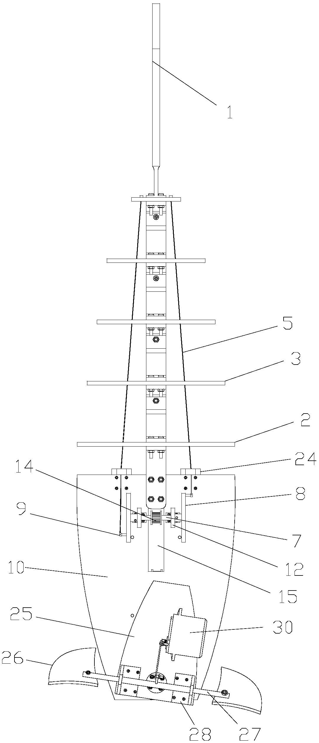
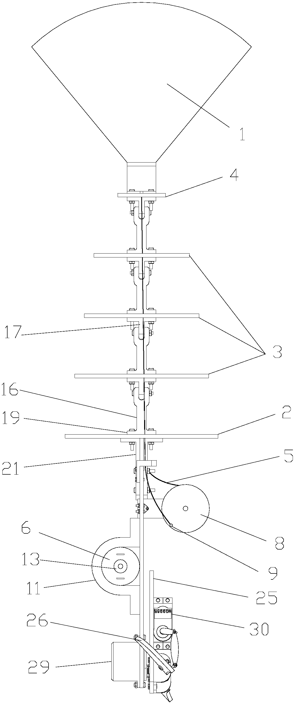
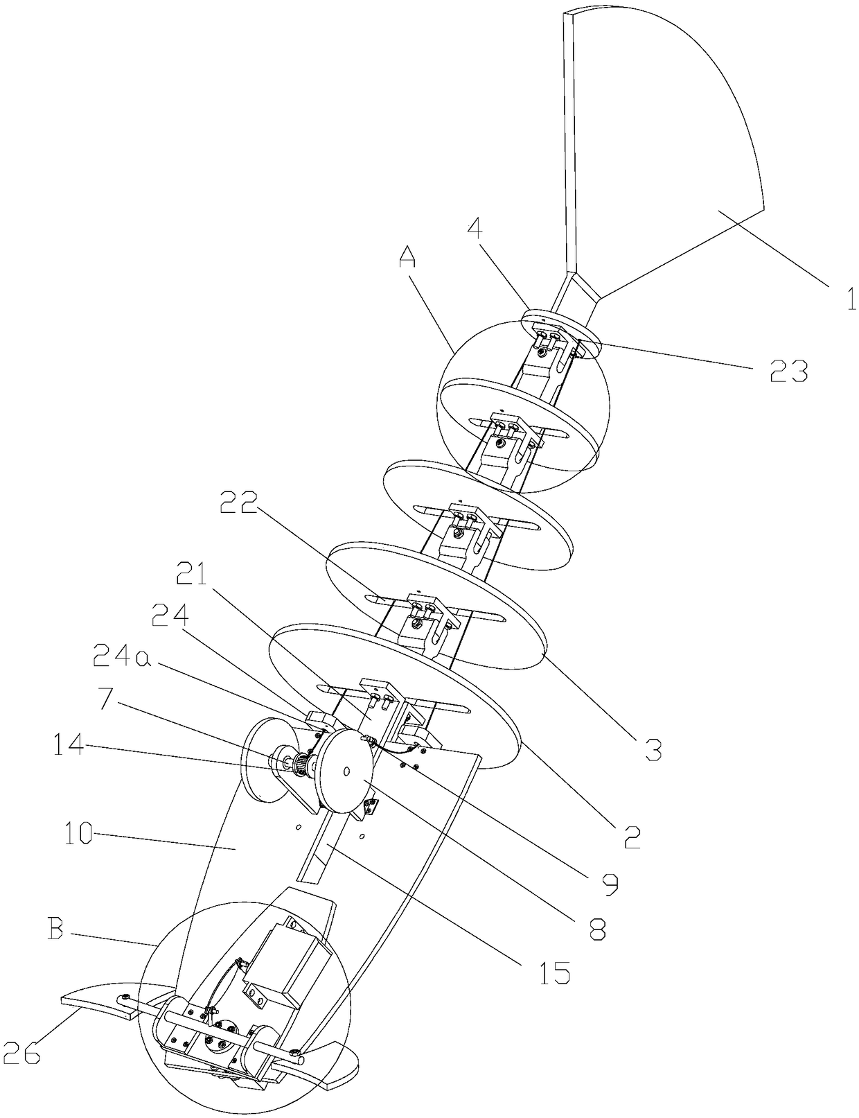
[0024] Such as Figure 1 to Figure 5 Shown: the wire-driven robotic fish of this embodiment includes fish head, fish body and fish tail connected in sequence, the fish tail includes caudal fin 1 and a support plate assembly, and the support plate assembly is sequentially connected from front to back One support plate I2, at least one support plate II3 and one support plate III4, the front side of the support plate I2 is fixedly connected to the fish body, the rear side of the support plate III4 is fixedly connected to the tail fin 1, the support plate I2 It is connected with the support plate II3, between the adjacent support plates II3 and between the support plate II3 and the support plate III4 through joint components;...


PUM


Abstract

A line-driven robotic fish including fish head, fish body and tail, Fish tail comprise a tail fin and a support plate assembly, The support plate assembly is composed of a support plate connected in turn from the rear to the rear, at least one support plate II and one support plate III, wherein the front side of the support plate I is fixedly connected with the fish body, the rear side of the support plate III is fixedly connected with the caudal fin, the support plate I and the support plate II are connected with each other, and the adjacent support plates II and the support plate II and thesupport plate III are connected with each other through joint components; And two transmission wires arranged in parallel. The front end of the transmission wire is connected with the fish tail driving mechanism, and the rear end passes through the support plate I and the support plate II in turn and is fixedly connected with the support plate III after passing through the support plate I and thesupport plate II; The two driving wires are made of flexible material and are driven by the fish tail driving mechanism, so as to drive the supporting plates II and III to swing left and right; The thread-driven type robot fish of the invention has simple joint structure and reduces the whole weight of the robot fish while providing its own driving force.

Description

technical field [0001] The invention relates to the field of bionic robots, in particular to a line-driven robotic fish. Background technique [0002] Fish swimming has the advantages of high efficiency, maneuverability and low noise. Therefore, the research of bionic robotic fish has become a hot spot in the field of robot research. With the continuous deepening of research on bionic robotic fish, bionic robotic fish is playing an important role in the fields of underwater search and rescue, water quality detection and marine resource exploration. The bionic robot fish is based on simplifying the propulsion motion of the fish to the continuous and periodic deformation of the fish body under ideal conditions. As a new type of underwater robot, the bionic mechanical fish can adapt to the challenges brought by the requirements of complex environment and efficient operation, so it has been extensively researched and developed. [0003] With the continuous development of bion...

Claims


Application Information

Patent Timeline
Patent Type & Authority Applications(China)
IPC IPC(8): B63H1/36
CPCB63H1/36
Inventor 罗强蔡黎罗洋郑岩
Owner CHONGQING THREE GORGES UNIV
Why Eureka
Try Eureka