A continuously variable camber structure of an aircraft and a decentralized driving control method thereof

A technology of aircraft and camber, applied in the field of aviation, can solve the problems of discontinuous shape and decreased aerodynamic efficiency, and achieve the effect of smooth and continuous shape, direct and efficient effect, and obvious benefits

Inactive Publication Date: 2018-12-21
SHENYANG AIRCRAFT DESIGN INST AVIATION IND CORP OF CHINA
View PDF6 Cites 14 Cited by
  • Summary
  • Abstract
  • Description
  • Claims
  • Application Information

AI Technical Summary

Problems solved by technology

[0004] The aircraft continuously variable camber structure and its distributed drive control method of the present invention can solve the problems of reduced aerodynamic efficiency and discontinuous shape of the existing aircraft control surfaces during deflection

Method used


Image

  • A continuously variable camber structure of an aircraft and a decentralized driving control method thereof
  • A continuously variable camber structure of an aircraft and a decentralized driving control method thereof
  • A continuously variable camber structure of an aircraft and a decentralized driving control method thereof

Examples


Embodiment 1

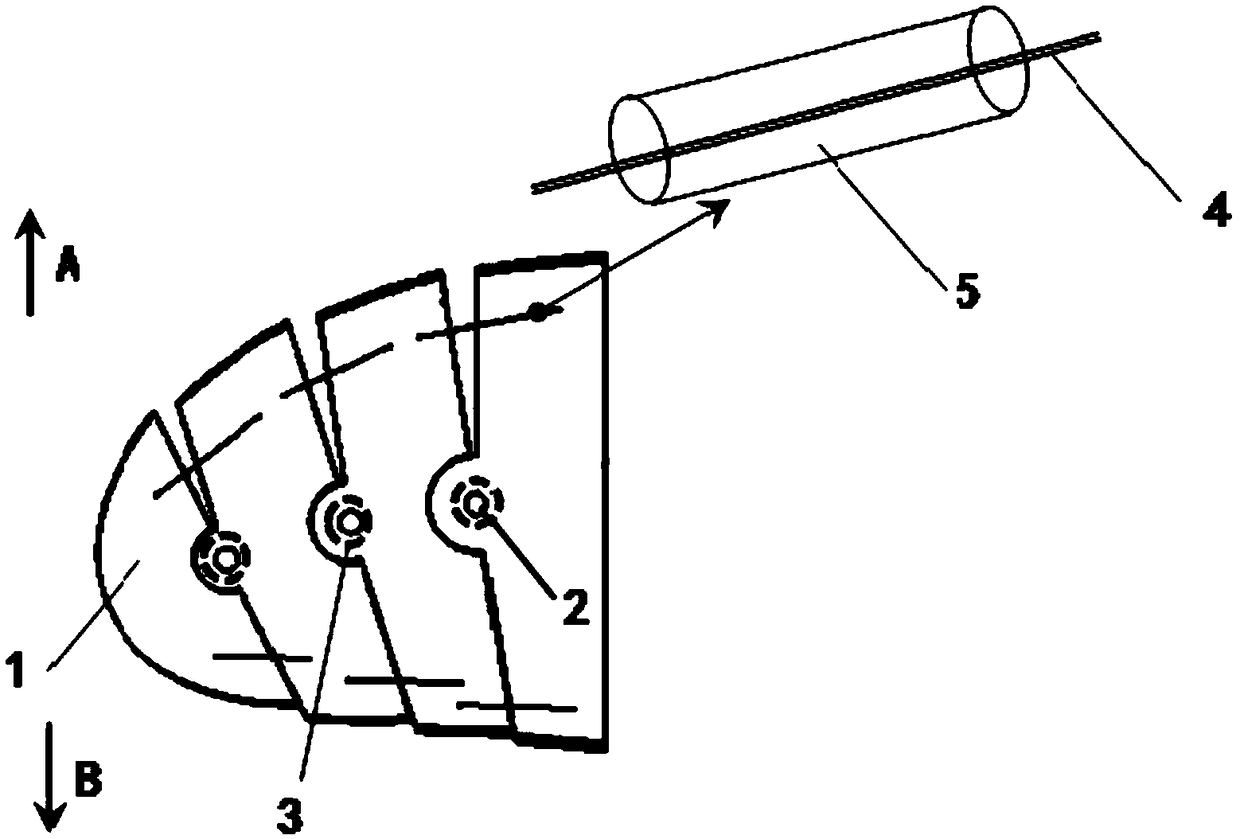
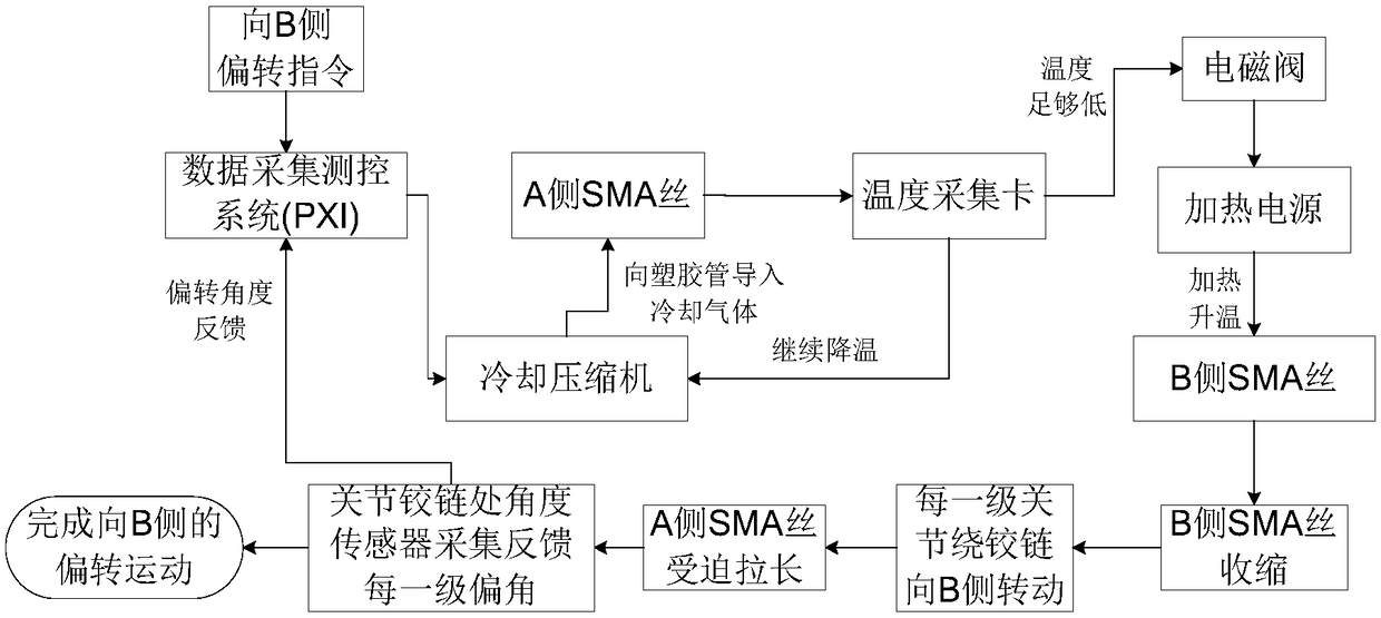
[0030] Such as image 3 , the data acquisition measurement and control system (PXI) inputs the deflection command to the B side, the measurement and control system drives the cooling compressor to introduce cooling gas into the plastic pipe on the A side, and the temperature acquisition card monitors the temperature of the SMA wire on the A side in real time. When it is low, the solenoid valve is triggered to turn on the heating power supply, and the SMA wire on the B side is energized and heated, and the temperature of the SMA wire on the B side rises, causing the SMA wire on the B side to shrink and deform, and the rib joint 1 of each stage goes around the hinge 2 directions Side B rotates, and the SMA wire on side A is forced to elongate. The angle sensor 3 collects the deflection angle between the wing-rib joints 1 of each stage, and at the same time feeds back the deflection angle to the data acquisition measurement and control system (PXI) to realize the light of the stru...

Embodiment 2

[0032] Such as Figure 4 , the data acquisition measurement and control system (PXI) inputs the deflection command to the A side, the measurement and control system drives the cooling compressor to introduce cooling gas into the plastic pipe on the B side, and the temperature acquisition card monitors the temperature of the SMA wire on the B side in real time. When the temperature reaches enough When it is low, the solenoid valve is triggered to turn on the heating power supply, and the SMA wire on side A is energized and heated, and the temperature of the SMA wire on side A rises, causing the SMA wire on side A to shrink and deform. Side A rotates, and the SMA wire on side B is forced to elongate. The angle sensor 3 collects the deflection angle between the wing-rib joints 1 of each stage, and at the same time feeds back the deflection angle to the data acquisition measurement and control system (PXI) to realize the light of the structure toward the A side. forward deflection...


PUM


Abstract

The invention belongs to the field of aviation technology, in particular to a trailing edge and wing tip continuously variable camber structure and a decentralized driving control method thereof, theaircraft continuous camber structure of the present invention comprises SMA wires, for connecting the edges of two adjacent pterygoid joints on the same side of the hinge, and the SMA wire is connected with a heating power source and sealed with a plastic tube, A plastic tube is connected to the cooling compressor, An angle sensor is mounted on each hinge, SMA wires have shape memory function, Atlow temperature, that SMA wires can be elongate and deformed under the external force, and the shape of the fixed length can be kept. The SMA wire on one side is heated, and the SMA wires on the other side are cooled by the cool gas living in the house through a plastic tube, so that the whole wing-rib joint can be deflected to one side.

Description

technical field [0001] The invention belongs to the field of aviation technology, and in particular relates to an aircraft wing leading edge, trailing edge and wingtip continuously variable camber structure and a distributed drive control method thereof. Background technique [0002] The leading-edge flaps, trailing-edge flaps, ailerons, and winglets currently used on aircraft control surfaces can increase the maximum lift coefficient, improve the aerodynamic performance of the aircraft, and control the motion attitude of the aircraft through their deflection movement. [0003] The control surface of the existing aircraft is connected to the wing by hinges or slide rails. There are obvious discontinuous points and step gaps between the control surface and the wing. When the airflow passes by, it is easy to separate, which greatly affects the Aerodynamic efficiency, and cause wing buffeting, reducing the flight control quality of the aircraft. Contents of the invention [...

Claims


Application Information

Patent Timeline
Patent Type & Authority Applications(China)
IPC IPC(8): B64C3/44B64C3/50B64C3/36B64C9/00
CPCB64C3/36B64C3/44B64C3/50B64C9/00B64C2009/005
Inventor 吴斌王云俊陈旭颜
Owner SHENYANG AIRCRAFT DESIGN INST AVIATION IND CORP OF CHINA
Why Eureka
Try Eureka