
Rotary wheel type automobile stamping part conveying device

A technology for automobile stamping parts and transportation devices, which is applied in the direction of internal parts, etc., can solve the problems of low space utilization rate, inconvenience, and low space utilization rate of the device, and achieve high space utilization rate, reasonable structure, and space saving Effect

Inactive Publication Date: 2018-12-21
JIANGSU JINPAI AUTOMOTIVE PARTS CO LTD
View PDF1 Cites 4 Cited by
  • Summary
  • Abstract
  • Description
  • Claims
  • Application Information

AI Technical Summary

Problems solved by technology

However, the space utilization rate of the existing transportation device is extremely low, and the whole device can only load a row of stamping parts. For example, the utility model patent of "a movable tooling suitable for the transportation of automobile stamping parts" disclosed by the application number CN201520537569.1, this The space utilization rate of the device recorded in the patent is low, and only a few stamping parts can be installed, which requires frequent back and forth transportation, which is very inconvenient

Method used


Image

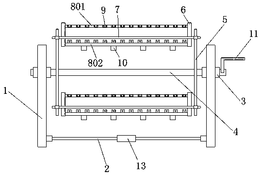
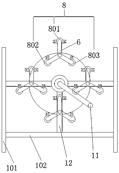
  • Rotary wheel type automobile stamping part conveying device
  • Rotary wheel type automobile stamping part conveying device

Examples


Embodiment Construction

[0020] The present invention will be further described below in conjunction with the embodiments and with reference to the accompanying drawings. It should be understood that the following specific embodiments are only used to illustrate the present invention and are not intended to limit the scope of the present invention. It should be noted that the words "front", "rear", "left", "right", "upper" and "lower" used in the following description refer to the direction in the figure, and the words "inner" and "outer ” refer to directions towards or away from the geometric center of a particular part, respectively.

[0021] As an embodiment of the present invention, a wheel-type automobile stamping parts transportation device described in conjunction with the accompanying drawings includes a vertical frame 1, and the vertical frame 1 is fixed by at least two vertical bars 101 and at least two horizontal bars 102. There are two vertical frames 1 that stand parallel to each other. T...


PUM


Abstract

The invention discloses a rotary wheel type automobile stamping part conveying device. The device comprises vertical frames, and each vertical frame is formed by fixedly connecting at least two vertical rods with at least two transverse rods. The vertical frames are opposite to each other in parallel, and the two vertical frames are detachably connected together by means of at least two connectingrods. Bearing blocks are fixedly connected to the two vertical frames, and rotating shafts which are rotationally connected with the bearing blocks are fixedly connected with two rotating discs. Fourgroups of stamping part storage components are fixedly connected between the two rotating discs, and the four groups of stamping part storage components are uniformly distributed on the rotating discs. The conveying device is reasonable in structure, large in space utilization rate and capable of storing more automobile stamping parts at a time, the frequency of back-and-forth transportation is reduced, the transportation time is saved, and the labor cost is reduced.

Description

technical field [0001] The invention relates to the technical field of automobile stamping parts processing, in particular to a wheel-type transportation device for automobile stamping parts. Background technique [0002] Automotive stampings, as the name suggests, are metal stampings that make up auto parts. Among automobile stamping parts, some parts become auto parts directly after stamping, and the other parts need to be welded, machined, or painted before they can become auto parts after stamping. There are many kinds of automobile stamping parts, such as automobile shock absorber stamping parts spring tray, spring seat, spring bracket, end cover, cover, compression valve cover, compression valve sleeve, oil seal seat, bottom cover, dust cover, impeller, oil Barrels, lugs, brackets, etc. all belong to automotive stampings. [0003] Currently, when transporting automobile stamped parts, especially when used to transport automobile fenders, cladding panels, etc., in ord...

Claims


Application Information

Patent Timeline
IPC IPC(8): B65D25/10B65D25/02
CPCB65D25/10B65D25/02
Inventor 陆宏娣
Owner JIANGSU JINPAI AUTOMOTIVE PARTS CO LTD
Learn More