flat knitting machine

A technology of flat knitting machines and needle beds, which is applied in the field of knitting machinery, and can solve problems such as the inability to adjust the gap between the needle beds, the restriction of the knitting effect of the flat knitting machine, and the inability to meet the knitting requirements, and achieve good adjustment effects, simple structure, and satisfactory adjustment. required effect

Active Publication Date: 2020-04-28
ZHEJIANG FENGFAN NC MACHINERY
View PDF9 Cites 1 Cited by
  • Summary
  • Abstract
  • Description
  • Claims
  • Application Information

AI Technical Summary

Problems solved by technology

[0004] Since the clearance of the needle bed of the existing flat knitting machine cannot be adjusted, the knitting effect of the flat knitting machine including the multi-gauge flat knitting machine is greatly restricted, and the fixed clearance of the needle bed also restricts the ability of the flat knitting machine to Knitting patterns, especially for more complex three-dimensional knitting, due to the large difference in thickness of different parts in the same knitting fabric, the fixed needle bed gap cannot meet the knitting requirements of this type of knitting fabric

Method used


Image

  • flat knitting machine
  • flat knitting machine
  • flat knitting machine

Examples


Embodiment 1

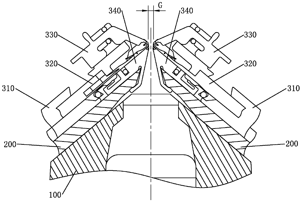
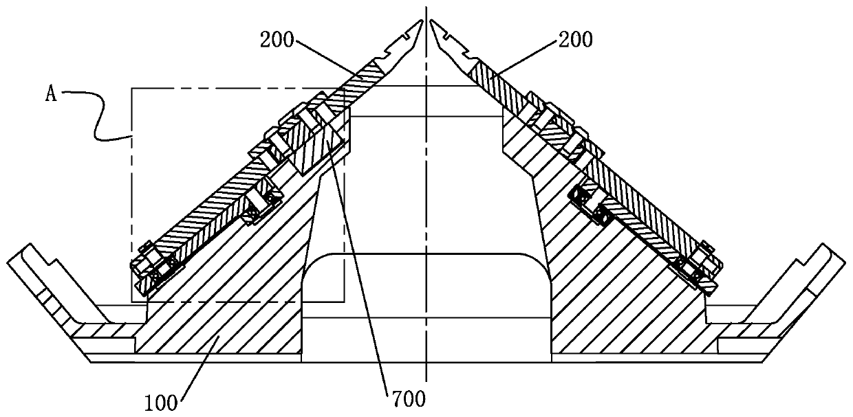
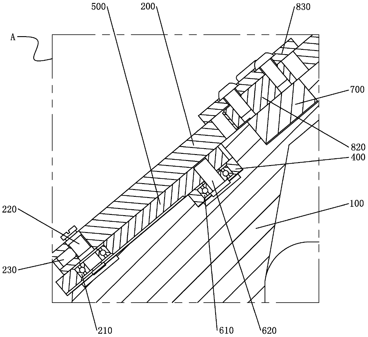
[0039] like figure 1 , figure 2 , image 3 , Figure 4 As shown, the flat knitting machine provided by Embodiment 1 of the present invention includes a needle bed base 100 and a needle bed 200. The needle bed base 100 is provided with two symmetrically inclined base surfaces 101, and the needle bed 200 is provided with two And be arranged on two base surfaces 101 respectively, on the front of needle bed 200, be provided with a plurality of inserting pieces 310 side by side at intervals, the front side of needle bed 200 is provided with tooth mouth plate 340 that is positioned at the front end of inserting piece 310, two needle beds A gap G between the tooth mouth pieces 340 on the 200 is provided. The flat knitting machine also includes an adjustment mechanism for adjusting the gap G of the needle bed plate mouth. The adjustment mechanism includes a horizontal adjustment piece, an oblique adjustment piece and a linkage piece. The horizontal adjustment piece is arranged on ...

Embodiment 2

[0059] like Figure 7As shown, Embodiment 2 of the present invention is an equivalent embodiment of the above-mentioned Embodiment 1. The difference between it and the above-mentioned Embodiment 1 is that the adjustment surface 402 is an inclined surface directly arranged on the transverse inner wall of the through groove 401, that is, it is arranged obliquely. A certain angle is set between the adjusting surface 402 of the sliding rail 400 and the length direction of the sliding rail 400 . This structure is beneficial to realize the stepless adjustment of the gap G of the needle bed, that is, the specific size of the gap G of the needle bed can be any value within the adjustment range, so as to better meet the adjustment requirements of the gap of the needle bed.

[0060] Specifically in this embodiment, since the left side of the adjustment surface 402 is higher, when the slide rail 400 moves laterally to the right, the adjustment plate 500 drives the needle bed 200 to rise ...

Embodiment 3

[0064] combine Figure 5 , Figure 8 Embodiment 3 of the present invention is an improved embodiment of the above-mentioned first embodiment, and its improvement relative to the above-mentioned first embodiment is that the positioning shaft 220 includes a first shaft section 221 and a second shaft section 222 whose axis centers are staggered, The first shaft section is rotatably inserted into the through hole 201 , the end surface of the first shaft section is provided with a "one"-shaped slot, and the support wheel 210 is rotatably sleeved on the second shaft section.

[0065] In order to fix the positioning shaft 220 , the needle bed 200 is also provided with a positioning hole 202 perpendicular to the through hole 201 , and a positioning pin 230 for fixing the positioning shaft 220 is provided in the positioning hole.

[0066] When the needle bed 200 is installed on the needle bed base 100, the specific position of the needle bed relative to the needle bed base can be effe...


PUM


Abstract

The invention discloses a flat knitting machine, and belongs to the field of knitting machinery. The flat knitting machine comprises a needle bed base and needle beds; multiple inserting pieces are arranged on the front face of each needle bed side by side at intervals, tooth notch pieces located on the lower portions of the front ends of the inserting pieces are arranged on the front sides of theneedle beds, and a needle bed plate opening gap is formed between the tooth notch pieces on the two needle beds; the flat knitting machine further comprises an adjusting mechanism which comprises a transverse adjusting part, oblique adjusting parts and linkage parts, the transverse adjusting part is arranged on the needle bed base and can move back and forth transversely relative to the needle bed base, when the oblique adjusting parts are connected to the needle beds, the linkage parts are arranged between the transverse adjusting part and the oblique transverse parts to be used for linkageof the transverse adjusting part and the oblique transverse parts, and when the transverse adjusting part moves transversely, the needle beds are driven by the linkage parts and the oblique adjustingparts to move vertically in the oblique direction of base planes of the needle beds to achieve needle bed plate opening gap adjustment. Accordingly, the purpose of adjusting the needle bed plate opening gap of a flat knitting machine with the specific size is achieved, and the knitting range of the flat knitting machine with the specific size is effectively widened conveniently.

Description

technical field [0001] The invention relates to the technical field of knitting machinery, in particular to a flat knitting machine. Background technique [0002] The flat knitting machine is a double-needle plate latch weft knitting machine. The cam device on the needle bed is like a set of flat cams. The stitches of the knitting needles can enter the grooves of the cams, and the moving cam forces the needles in the needle grooves of the needle bed. Regular up and down movements, the yarn can be woven into a knitted fabric through the action of the needle hook and the needle latch. Existing flat knitting machines have different gauges, and the flat knitting machines of each gauge can weave braids matching the gauge, the lower the gauge, the thicker the yarn used, and the thicker the braided fabric; The higher the number, the finer the yarn used and the thinner the braid weaves. Corresponding to the machine number is the distance between the two needle beds in the flat kni...

Claims


Application Information

Patent Timeline
Patent Type & Authority Patents(China)
IPC IPC(8): D04B7/00D04B15/12
CPCD04B7/00D04B15/12
Inventor 付洪平傅建新谢李平
Owner ZHEJIANG FENGFAN NC MACHINERY
Why Eureka
Try Eureka