
Use method for driving transmission device

A technology for driving transmission and transmission shafts, which is applied in the direction of transmission devices, fluid transmission devices, belts/chains/gears, etc., which can solve the problems of increasing the burden of travel, and achieve the effects of improving safety, convenient installation, and simple operation

Inactive Publication Date: 2018-12-21
叶机林
View PDF0 Cites 0 Cited by
  • Summary
  • Abstract
  • Description
  • Claims
  • Application Information

AI Technical Summary

Problems solved by technology

However, the current self-balancing scooter cannot achieve the same differential speed as a car to reduce the distance required for turning. At the same time, the self-balancing scooter on the market needs to get off the driver to carry it forward when encountering a staircase section, which increases the travel burden.

Method used


Image

  • Use method for driving transmission device
  • Use method for driving transmission device

Examples


Embodiment Construction

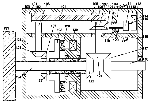
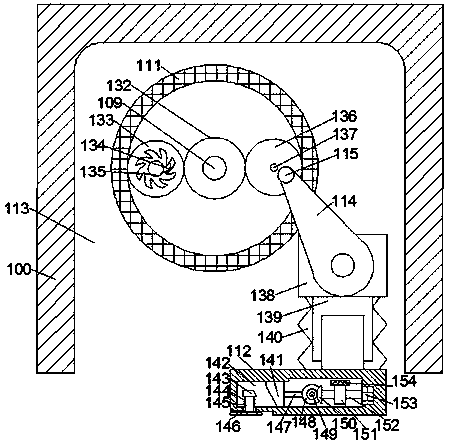
[0016] Combine below Figure 1-2 The present invention will be described in detail.

[0017] According to a method for using a driving transmission device of the present invention, a driving transmission device is used, and the driving transmission device includes a body 100 and a first cavity 101 arranged in the body 100, the body 100 A second cavity 126 located at the lower end of the first cavity 101 is provided inside, a power input cavity 116 located at the right end of the second cavity 126 is provided inside the fuselage 100, and a The climbing cavity 113 located at the right end of the first cavity 101, the inner wall of the bottom end of the first cavity 101 is rotatably connected with the first transmission shaft 103 which is located at the upper end of the second cavity 126 and extends up and down. The upper end of a transmission shaft 103 is provided with a first pulley 102, the lower end of the first transmission shaft 103 is provided with a first bevel gear 125 ...


PUM


Abstract

The invention discloses a use method for a driving transmission device. In the method, a driving transmission device is used. The driving transmission device comprises a device body and a first cavityarranged in the device body; a second cavity located at the lower end of the first cavity is arranged in the device body; a power input cavity located at the right end of the second cavity is arranged in the device body; a climbing cavity located at the right end of the first cavity is arranged in the device body; the inner wall of the bottom end of the first cavity is connected in a running fitmanner with a first transmission shaft which is located at the upper end of the second cavity and extends vertically; a first belt pulley is arranged at the tail end of the upper end of the first transmission shaft; a first bevel gear located in the second cavity is arranged at the tail end of the lower end of the first transmission shaft; and the interior of the first cavity is connected in a running fit manner with a second transmission shaft which is located at the right end of the first transmission shaft and extends vertically in a running fit manner. The use method disclosed by the invention has a high linkage property; the differential transformation is accomplished by the interaction of magnetic mechanisms to achieve a small-range turning; and the forward travelling and climbing are completed synchronously through a planetary gear set.

Description

technical field [0001] The invention relates to the technical field of walking tools, in particular to a method for using a driving transmission device. Background technique [0002] With the rapid development of science and technology, human beings have developed more compact walking balance vehicles and so on. However, the current self-balancing scooter cannot achieve the same differential speed as a car to reduce the distance required for turning. At the same time, the self-balancing scooter on the market needs to get off the driver to carry it forward when it encounters a staircase section, which increases the travel burden. Therefore a kind of walking-replacing tool that can realize differential turning and climbing stairs becomes the inevitable trend of today's development, and a kind of novel drive transmission device that can solve the appeal problem that the present invention clarifies. Contents of the invention [0003] The purpose of the present invention is to...

Claims


Application Information

Patent Timeline
Patent Type & Authority Applications(China)
IPC IPC(8): F16H47/04
CPCF16H47/04
Inventor 叶机林
Owner 叶机林
Learn More