
Novel bypass quick connector

A fast and new technology of bypass, applied in the direction of branch pipelines, pipes, pipes/pipe joints/fittings, etc., can solve the problems of inconvenient connection between bypass and branch pipes, and solve the problems of bypass water leakage and time-consuming and laborious installation. Inexpensive and easy to use

Pending Publication Date: 2018-12-21
河北省农林科学院农业信息与经济研究所 +1
View PDF0 Cites 0 Cited by
  • Summary
  • Abstract
  • Description
  • Claims
  • Application Information

AI Technical Summary

Problems solved by technology

[0007] The technical problem solved by the invention is the inconvenient connection between the bypass and the branch pipe, and a bypass quick-connector is provided, which has the characteristics of simple structure, convenient use, and low price.

Method used


Image

  • Novel bypass quick connector
  • Novel bypass quick connector
  • Novel bypass quick connector

Examples


Embodiment

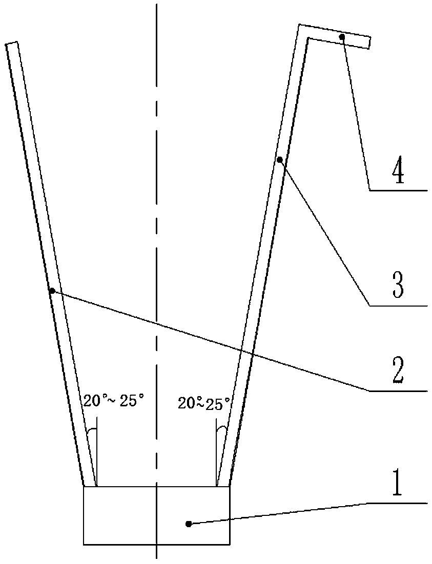
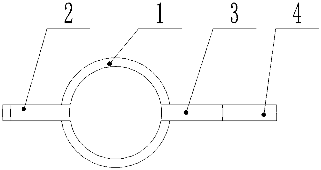
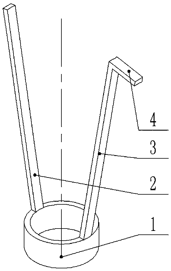
[0026] like figure 1 , figure 2 , image 3 As shown, a new type of bypass quick-connector, select two steel wires or steel plates sufficient to support the U-shaped nut cap and weld them on the outer edge of the base 1, the base 1 is cut from a circular steel pipe or iron pipe, and two The connection line of the steel plate or steel wire passes through the center of the base 1, and a part of the top of one steel wire or steel plate is bent to form the bending head 4, so that it is in a vertical state with the bending part 3, and the other steel wire or steel plate 2 is kept straight. .

[0027] A further preferred technical solution is that the two steel wires or steel plates have different lengths and are used to fix and vertically center the U-shaped nut cap.

[0028] A further optimal technical solution is that the two steel wires or steel plates are inclined outwards, 20°-25° from the vertical direction, because it is necessary to support the bypass pipe / bypass valve, ...


PUM

PropertyMeasurementUnit
Lengthaaaaaaaaaa

Abstract

The invention relates to a novel bypass quick connector, and belongs to the technical field of irrigation. According to the novel bypass quick connector, two steel plates or steel wires with higher strength range elasticity are chosen, the length is 1.5 times the length of a bypass pipe or a bypass valve, the lengths of the two steel plates or the steel wires are different, and a round pipe is chosen as a base. The two steel plates or the steel wires are spot-welded to the outer edge of the base round pipe separately, the connecting lines of the two steel plates or the steel wires pass throughthe circle center of the base, and the steel plates or the steel wires are kept at an angle of about 20 degrees to the axis of the base in the vertical direction. The longer steel plate or wire is selected, part of the top end of the steel plate or the steel wire is bent to be vertical to the steel plate or wire, the length of the top end part is more than 3mm, the top end part is used for fixinga U-shaped nut cap, and the head of the other steel plate or the steel wire is kept straight so that the bypass quick connector can be removed from the bypass pipe or the bypass valve. The novel bypass quick connector can more effectively solve the problems of bypass leakage and time-consuming and labor-consuming installation, and is simple in structure, convenient to use and low in price.

Description

technical field [0001] The invention belongs to the technical field of irrigation, and in particular relates to a novel bypass quick-connector. Background technique [0002] The bypass is an essential connecting device for branch pipes and capillary pipes in micro-irrigation irrigation technology. Irrigation requires the bypass valve to be watertight and easy to connect. There are two ways to connect the bypass in common use at present. One is to plug the U-shaped nut cap on the bypass valve into the branch pipe from the hole after the puncher punches the hole, and then align and tighten with the remaining part of the bypass. [0003] The problem that it exists is, because the U-shaped nut cap is larger than the orifice, it is easy to cause the orifice on the branch pipe to tear and leak when it is firmly inserted into the branch pipe. [0004] The second is to put the U-shaped nut cap from the near opening end of the branch pipe, and move the U-shaped nut cap to align and...

Claims


Application Information

Patent Timeline
IPC IPC(8): F16L41/08F16L41/16
CPCF16L41/08F16L41/16
Inventor 贾建明范凤翠刘胜尧高清海闫立波马春红张西群赵璞石玉芳耿计申
Owner 河北省农林科学院农业信息与经济研究所
Learn More